EVL6566A-75WES4 STMicroelectronics, EVL6566A-75WES4 Datasheet - Page 32
EVL6566A-75WES4
Manufacturer Part Number
EVL6566A-75WES4
Description
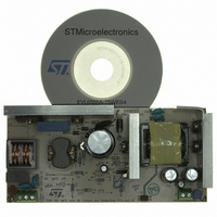
BOARD DEMO FOR L6563/LL6566A
Manufacturer
STMicroelectronics
Type
Power Factor Correctionr
Specifications of EVL6566A-75WES4
Main Purpose
AC/DC, Primary and Secondary Side with PFC
Outputs And Type
1, Isolated
Power - Output
75W
Voltage - Output
19V
Current - Output
4A
Voltage - Input
90 ~ 264VAC
Regulator Topology
Flyback
Board Type
Fully Populated
Utilized Ic / Part
L6563, L6566A, TSM1014
Input Voltage
90 V to 264 V
Output Voltage
19 V
Dimensions
78 mm x 170 mm
Product
Power Management Modules
Lead Free Status / RoHS Status
Lead free / RoHS Compliant
Frequency - Switching
-
Lead Free Status / Rohs Status
Lead free / RoHS Compliant
For Use With/related Products
L6563S, L6566A
Other names
497-8834
Available stocks
Company
Part Number
Manufacturer
Quantity
Price


Application information
5.9
32/51
Figure 19. Possible interfaces between the L6566A and a PFC controller
To prevent intermittent operation of the PFC stage, some hysteresis is provided: if the
internal switch is open, it will be closed (which will re-enable the PFC pre-regulator) when
V
transients V
the Vcc_PFC pin to open. Entering burst-mode (V
immediately.
Besides pin 6 going open, when V
below to compensate for the drop of the voltage delivered by the self-supply circuit that
occurs at light load (see
Latched disable function
The device is equipped with a comparator having the non-inverting input externally available
at the pin DIS (8) and with the inverting input internally referenced to 4.5 V. As the voltage
on the pin exceeds the internal threshold, the device is immediately shut down and its
consumption reduced to a low value.
The information is latched and it is necessary to let the voltage on the Vcc pin go below the
UVLO threshold to reset the latch and restart the device. To keep the latch supplied as long
as the converter is connected to the input source, the HV generator is activated periodically
so that Vcc oscillates between the start-up threshold V
HV generator in this way cuts its power dissipation approximately by three (as compared to
the case of continuous conduction) and keeps peak silicon temperature close to the average
value.
To let the L6566A restart it is then necessary to disconnect the converter from the input
source. Pulling pin 16 (AC_OK) below the disable threshold (see
protection on page 38
latch can be cleared and a quicker restart is allowed as the input source is removed. This
operation is shown in the timing diagram of
This function is useful to implement a latched overtemperature protection very easily by
biasing the pin with a divider from VREF, where the upper resistor is an NTC physically
located close to a heating element like the MOSFET, or the transformer. The DIS pin is a
high impedance input, thus it is prone to pick up noise, which might give origin to undesired
latch-off of the device. It is possible to bypass the pin to ground with a small film capacitor
(e.g. 1-10 nF) to prevent any malfunctioning of this kind.
COMP
exceeds V
COMP
must stay below V
COMPL
) will stop the HV generator until Vcc falls below Vcc
Vcc
Vcc
Section 5.4: Adaptive UVLO on page 25
5
5
> V
COMPO
L6566A
L6566A
COMP
. Additionally, to reject V
COMPO
falls below V
6
6
Figure 20
for more than 1024 oscillator cycles in order for
Vcc_PFC
Vcc_PFC
22 kΩ
COMP
4.7k Ω
COMPO
.
ccON
< V
RUN
Vcc
10
and V
COMPBM
COMP
the UVLO threshold is set 2.4 V
L6563
L6561
L6562
L6563
).
ccON
Section 5.12: Brownout
undershoots during
) will open Vcc_PFC
- 0.5 V. Activating the
restart
, so that the
L6566A
Related parts for EVL6566A-75WES4
Image
Part Number
Description
Manufacturer
Datasheet
Request
R

Part Number:
Description:
BOARD EVAL FOR L6566A
Manufacturer:
STMicroelectronics
Datasheet:

Part Number:
Description:
STMicroelectronics [RIPPLE-CARRY BINARY COUNTER/DIVIDERS]
Manufacturer:
STMicroelectronics
Datasheet:
Part Number:
Description:
STMicroelectronics [LIQUID-CRYSTAL DISPLAY DRIVERS]
Manufacturer:
STMicroelectronics
Datasheet:

Part Number:
Description:
BOARD EVAL FOR MEMS SENSORS
Manufacturer:
STMicroelectronics
Datasheet:
Part Number:
Description:
NPN TRANSISTOR POWER MODULE
Manufacturer:
STMicroelectronics
Datasheet:
Part Number:
Description:
TURBOSWITCH ULTRA-FAST HIGH VOLTAGE DIODE
Manufacturer:
STMicroelectronics
Datasheet:
Part Number:
Description:
Manufacturer:
STMicroelectronics
Datasheet:
Part Number:
Description:
DIODE / SCR MODULE
Manufacturer:
STMicroelectronics
Datasheet:
Part Number:
Description:
DIODE / SCR MODULE
Manufacturer:
STMicroelectronics
Datasheet:
Part Number:
Description:
Search -----> STE16N100
Manufacturer:
STMicroelectronics
Datasheet:
Part Number:
Description:
Search ---> STE53NA50
Manufacturer:
STMicroelectronics
Datasheet:
Part Number:
Description:
NPN Transistor Power Module
Manufacturer:
STMicroelectronics
Datasheet: