EVL6566A-75WES4 STMicroelectronics, EVL6566A-75WES4 Datasheet - Page 38
EVL6566A-75WES4
Manufacturer Part Number
EVL6566A-75WES4
Description
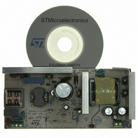
BOARD DEMO FOR L6563/LL6566A
Manufacturer
STMicroelectronics
Type
Power Factor Correctionr
Specifications of EVL6566A-75WES4
Main Purpose
AC/DC, Primary and Secondary Side with PFC
Outputs And Type
1, Isolated
Power - Output
75W
Voltage - Output
19V
Current - Output
4A
Voltage - Input
90 ~ 264VAC
Regulator Topology
Flyback
Board Type
Fully Populated
Utilized Ic / Part
L6563, L6566A, TSM1014
Input Voltage
90 V to 264 V
Output Voltage
19 V
Dimensions
78 mm x 170 mm
Product
Power Management Modules
Lead Free Status / RoHS Status
Lead free / RoHS Compliant
Frequency - Switching
-
Lead Free Status / Rohs Status
Lead free / RoHS Compliant
For Use With/related Products
L6563S, L6566A
Other names
497-8834
Available stocks
Company
Part Number
Manufacturer
Quantity
Price


Application information
5.12
38/51
Brownout protection
Brownout protection is basically a not-latched device shutdown function activated when a
condition of mains undervoltage is detected. There are several reasons why it may be
desirable to shut down a converter during a brownout condition, which occurs when the
mains voltage falls below the minimum specification of normal operation.
Firstly, a brownout condition may cause overheating of the PFC front-end due to an excess
of RMS current. Secondly, brownout can also cause the PFC pre-regulator to work open
loop. This could be dangerous to the PFC itself and the downstream converter, should the
input voltage return abruptly to its rated value, given the slow response of PFC to transient
events. Finally, spurious restarts may occur during converter power down, hence causing
the output voltage not to decay to zero monotonically.
L6566A shutdown upon brownout is accomplished by means of an internal comparator, as
shown in the block diagram of
input of the comparator, available on the AC_OK pin (16), is supposed to sense a voltage
proportional to either the RMS or the peak mains voltage; the non-inverting input is
internally referenced to 0.485 V with 35 mV hysteresis. If the voltage applied on the AC_OK
pin before the device starts operating does not exceed 0.485 V or if it falls below 0.45 V
while the device is running, The AC_OK signal goes high, the pin Vcc_PFC is open and the
device shuts down, with the soft-start capacitor discharged and the gate-drive output low.
Additionally, in case the device has been latched off by some protection function (in which
case Vcc is oscillating between V
0.45 V will clear the latch. This feature can be used to allow a quicker restart as the input
source is removed.
Figure 25. Brownout protection: internal block diagram and timing diagram
Sensed
R
R
voltage
H
L
AC_OK
16
L6566A
15 µA
0.485V
0.45V
Vcc
+
-
Figure 25
5
ccON
AC_FAIL
and V
, which shows the basic circuit usage. The inverting
ccON
Sensed voltage
Vsen
Vcc_PFC
VAC_OK
Vsen
(pin 16)
AC_FAIL
(pin 6)
- 0.5 V) the AC_OK voltage falling below
(pin 5)
(pin 4)
15 µA
Vcc
GD
Vout
OFF
I
HYS
ON
0.485V
L6566A
0.45V
t
t
t
t
t
t
t
t
Related parts for EVL6566A-75WES4
Image
Part Number
Description
Manufacturer
Datasheet
Request
R

Part Number:
Description:
BOARD EVAL FOR L6566A
Manufacturer:
STMicroelectronics
Datasheet:

Part Number:
Description:
STMicroelectronics [RIPPLE-CARRY BINARY COUNTER/DIVIDERS]
Manufacturer:
STMicroelectronics
Datasheet:
Part Number:
Description:
STMicroelectronics [LIQUID-CRYSTAL DISPLAY DRIVERS]
Manufacturer:
STMicroelectronics
Datasheet:

Part Number:
Description:
BOARD EVAL FOR MEMS SENSORS
Manufacturer:
STMicroelectronics
Datasheet:
Part Number:
Description:
NPN TRANSISTOR POWER MODULE
Manufacturer:
STMicroelectronics
Datasheet:
Part Number:
Description:
TURBOSWITCH ULTRA-FAST HIGH VOLTAGE DIODE
Manufacturer:
STMicroelectronics
Datasheet:
Part Number:
Description:
Manufacturer:
STMicroelectronics
Datasheet:
Part Number:
Description:
DIODE / SCR MODULE
Manufacturer:
STMicroelectronics
Datasheet:
Part Number:
Description:
DIODE / SCR MODULE
Manufacturer:
STMicroelectronics
Datasheet:
Part Number:
Description:
Search -----> STE16N100
Manufacturer:
STMicroelectronics
Datasheet:
Part Number:
Description:
Search ---> STE53NA50
Manufacturer:
STMicroelectronics
Datasheet:
Part Number:
Description:
NPN Transistor Power Module
Manufacturer:
STMicroelectronics
Datasheet: