SI3461-KIT Silicon Laboratories Inc, SI3461-KIT Datasheet
SI3461-KIT
Specifications of SI3461-KIT


Related parts for SI3461-KIT

SI3461-KIT Summary of contents
Page 1
... The Si3461 is a single-port power management controller for IEEE 802.3at PoE/PoE+ compliant Power Sourcing Equipment (PSE). The Si3461 operates directly from (nominal) isolated input for PoE (nominal) isolated input for PoE+. The complete Si3461 reference design (i.e., the Si3461-EVB) also provides full IEEE-compliant classification and detection as well as a robust disconnect algorithm ...
Page 2
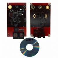
... Si3461-EVB 3. Connectors and Switches The Si3461-EVB is equipped with two banana jacks and an optional third banana jack on one side and two RJ-45 connectors on the other side. Figure 2. Placement of Connectors and Switches The board receives power through the banana jacks: J1 BLACK banana jack: ...
Page 3
... Connect the 50 V power supply to the banana inputs observing the correct polarity (a series diode protects the board from damage in case of polarity reversal). Switch on the 50 V power supply. The status LED should flash at a 1.5 Hz rate signaling that the Si3461 is trying to detect a PD. ...
Page 4
... A or B), the location of power insertion (Endpoint or Midspan), and 10BASE-T/100BASE-TX or 1000BASE-T compatibility. The Si3461-EVB implements the configuration shown in Figure 4. Midspan PSE connection (Alternative B), but the Si3461 controller can be configured to operate in either Midspan or Endpoint applications and may be designed in applications using any pairs. SWITCH/HUB ...
Page 5
... For endpoint applications, detection must be completed within 500 ms of applying a valid signature. When configured as a midspan, there is a possibility that the PSE circuit will compete with an endpoint PSE, and, as required by the IEEE specifications, the Si3461 waits at least two seconds after an unsuccessful detection cycle to repeat the detection process. ...
Page 6
... The Si3461-EVB implements both the one-event and two-event physical layer classification methods set up for available power, it attempts to classify a Type2 PD first by the two event method. If the detected class is other than Class 4 or there is less than power available, the Si3461 tries to classify a Type1 PD using the one event method. ...
Page 7
... Output Voltage and Load Current Waveforms" on page 12. 6.1. Initialization and Operating Mode Configuration The Si3461 is initialized at powerup or whenever Pin 8 (RST) is held low and then allowed to transition high. Upon reset (RST asserted low), the voltage at the STATUS pin (as determined by the DIP switch and the associated resistor network) is sensed to determine the operating mode of the Si3461 ...
Page 8
... For the two-event classification, the 18 V pulse is output twice with an 8.5 V amplitude mark pulse for 10 ms between the two classification pulses. If the available power set by the initial voltage on the Si3461's STATUS pin during startup the Si3461-EVB first attempts to classify a Type 2 PD using the two-event method. If, at the end of the first event, something other ...
Page 9
... For less than available power, only the one-event method is used. In this case Class detected, only 15 power is granted. If the class level of the PD is not within the supported level as set by the initial voltage on the Si3461's STATUS pin (refer to the Operating Mode Configuration section above), an error is declared, and the LED blinks rapidly at a rate for two seconds before the Si3461 goes back to the detection cycle ...
Page 10
... Si3461-EVB's RJ-45 jack labelled "PoE". Power will not be provided until an open-circuit condition is detected. Once the Si3461-EVB detects an open-circuit condition, the detection process begins. The status LED blinks at a rate of 1.5 Hz, and the Si3461 is then allowed to go into classification and powerup mode if a valid PD signature resistance is detected. ...
Page 11
... If the input power supply is referenced to earth ground and if one of the output pads is connected to ground, it can create a high-current fault condition that will not be protected. 7.3. SELV-Compliant Output Voltage Since the output of the Si3461-EVB reference design is designed to be less than 57 Vdc under all conditions considered an SELV circuit. 7.4. Surge Protection The Si3461-EVB applications design includes a clamp diode, D6, to protect against 50 µ ...
Page 12
... Si3461-EVB 8. Output Voltage and Load Current Waveforms Figures 6 through 13 show the output voltage and load current waveforms during startup and fault conditions. Refer also to the Si3461-EVB schematics in Figures 14 through 16. Ch1: PoE output voltage referenced to the +50V rail Bad detection signature detected at this point Figure 6 ...
Page 13
... Ch1: PoE output voltage referenced to the +50V rail Detection Figure 8. Detection and Classification Pulse for a Type-1 Device Ch1: PoE output voltage referenced to the +50V rail Detection Figure 9. Detection and Classification Pulse for a Type-2 Device Rev. 0.5 Si3461-EVB Classification Mark Pulse Two event classification 13 ...
Page 14
... Si3461-EVB Ch1: PoE output voltage referenced to the +50V rail Detection Figure 10. Detection, Classification, and Powerup for a Type-1 Device Ch1: PoE output voltage referenced to the +50V rail Detection Figure 11. Detection, Classification, and Power-up for a Type-2 Device 14 Classification Power-on Mark Pulse Two event classification Power-on Rev ...
Page 15
... Figure 12. Overcurrent Disconnect Delay Time Figure 13. Overcurrent Disconnect Delay Time Rev. 0.5 Si3461-EVB 15 ...
Page 16
... Si3461-EVB 9. Si3461-EVB Schematics Full schematics are provided in the following figures. To ensure you are using the latest schematic database revisions, you may download the zip file from the Silicon Laboratories Si3461 documentation page: http://www.silabs.com/products/power/poe/Pages/PowerSourcingEquipment.aspx GND 11 VDD 3 PUSHBUTTON SW PUSHBUTTON 470pF 470pF C9 C9 ...
Page 17
... Si3461-EVB Rev. 0.5 17 ...
Page 18
... Si3461-EVB 18 Rev. 0.5 ...
Page 19
... FA2536-ALD 675 µH Q1,Q2, 5 Q3,Q5, MMBTA06LT1 500 IRFM120A 2.3 A Q14,Q16, 3 BC856A 100 mA Q17 5.11 k 2 R1b,R1a 2 W Table 4. Si3461-EVB Bill of Materials PCB Tol Dielectric Footprint ±10% X7R C0603 ±20% X5R C0603 ±20% Al Electr. C2.5X6.3MM-RAD ±10% X7R C1210 ±10% X7R C0603 ±10% ...
Page 20
... Si3461-EVB Table 4. Si3461-EVB Bill of Materials (Continued) Qty Ref Value Rating 1 k 2 R2,R19 1/10 W 66.5 k 1/10 W 40.2 k 1/10 W 49.9 k 1/8 W 1.5 k 1/10 W 332 1/10 W 549 k 1/10 W 2.15 k 1/10 W R10,R28 3 1/16 W R29 R11,R12 ...
Page 21
... Si3461-EVB PCB Layouts Full PCB layouts are provided in the following figures. To ensure you are using the latest layout database revisions, you may download the zip file from the Silicon Laboratories Si3461 documentation page: http://www.silabs.com/products/power/poe/Pages/PowerSourcingEquipment.aspx Si3461-EVB Rev. 0.5 21 ...
Page 22
... Si3461-EVB 22 Rev. 0.5 ...
Page 23
... Si3461-EVB Rev. 0.5 23 ...
Page 24
... Si3461-EVB 24 Rev. 0.5 ...
Page 25
... Si3461-EVB Rev. 0.5 25 ...
Page 26
... Other component considerations: Headers J10 and J11 are used for development purposes only. The Si3461 is not user-programmable, and it is not recommended that these components be included in actual layouts. The operating mode setting DIP switch and its associated resistors are probably not needed in a custom design. Replace them with a suitable voltage divider consisting of two resistors (preferably with a resulting 2.0 k ...
Page 27
... Operating the Si3461-EVB The Si3461-EVB itself is very simple to use. Only power source is needed for connection to J2. A power rating of at least recommended when the high-power PoE+ mode is used. The Si3461 will automatically power up, detect the operational modes (midspan/endpoint, classification power level, and restart mode), and begin the detection process, during which the LED flashes at 1.5 times per second. ...
Page 28
... PSE system designers who require IEEE-compliant PSE functionality and safe operation with standard telephone interfaces and voltages. 15. Ordering Guide Ordering Part Number Si3461-KIT Evaluation board kit for Si3461-EVB reference design. Ordering part number for Si3461 devices. Si3461-XYY- device revision firmware revision. ...
Page 29
... Updated “10. Si3461-EVB Bill of Materials”. Revision 0.3 to Revision 0.4 Updated firmware revision to 0.3. Updated schematic in Figure 14 on page 16. Updated "10. Si3461-EVB Bill of Materials" on page 19. Revision 0.4 to Revision 0.5 Maintained consistency with firmware Revision 0.2. ...
Page 30
... Si3461-EVB C I ONTACT NFORMATION Silicon Laboratories Inc. 400 West Cesar Chavez Austin, TX 78701 Tel: 1+(512) 416-8500 Fax: 1+(512) 416-9669 Toll Free: 1+(877) 444-3032 Please visit the Silicon Labs Technical Support web page: https://www.silabs.com/support/pages/contacttechnicalsupport.aspx and register to submit a technical support request. The information in this document is believed to be accurate in all respects at the time of publication but is subject to change without notice. ...