SI3461-KIT Silicon Laboratories Inc, SI3461-KIT Datasheet - Page 27
SI3461-KIT
Manufacturer Part Number
SI3461-KIT
Description
BOARD EVAL FOR SI3461
Manufacturer
Silicon Laboratories Inc
Type
Controllers & Processorsr
Specifications of SI3461-KIT
Main Purpose
Special Purpose DC/DC, Power Over Ethernet
Board Type
Fully Populated
Utilized Ic / Part
Si3461
Ethernet Connection Type
10/100 Base-T, IEEE 802.3
Interface Type
Ethernet
Operating Voltage
12 V to 15 V
Operating Current
10 mA
Product
Modules
For Use With/related Products
Si3460
Lead Free Status / RoHS Status
Lead free / RoHS non-compliant
Current - Output
-
Voltage - Output
-
Voltage - Input
-
Power - Output
-
Frequency - Switching
-
Outputs And Type
-
Regulator Topology
-
Lead Free Status / Rohs Status
Lead free / RoHS Compliant
Other names
336-1843


Si3461-EVB
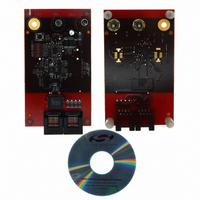
13. Operating the Si3461-EVB
The Si3461-EVB itself is very simple to use. Only a 50 V dc power source is needed for connection to J2. A power
rating of at least 35 W is recommended when the high-power PoE+ mode is used.
The Si3461 will automatically power up, detect the operational modes (midspan/endpoint, classification power
level, and restart mode), and begin the detection process, during which the LED flashes at 1.5 times per second.
Figure 22. Si3461-EVB
To test the Si3461-EVB in a PoE environment, many commercial PDs are available, such as Wireless Access
Points (WAPs), Voice over IP phones (VoIP), and IP-based security cameras. Any of these can be connected to the
Si3461-EVB to receive PSE power while exchanging Ethernet traffic. One example of a POE+ PD is an 802.11n
(multi-radio) wireless access point.
To test the Si3461-EVB in a PoE environment, many commercial PDs are available, such as Wireless Access
Points (WAPs), Voice over IP phones (VoIP), and IP-based security cameras. Any of these can be connected to the
Si3461-EVB to receive PSE power while exchanging Ethernet traffic.
Another PD option is to use the Si3461-EVB with one of the Si3400/01 or Si3402 evaluation boards configured to
present a Class 4 load if POE+ is desired. If one of these boards is used, it should be configured to present a
minimum load of > 0.25 W to ensure that it draws at least 10 mA to comply with the IEEE standard.
When the Si3461 is applying power to a valid PD, the LED is continuously lit. After an error condition (e.g., an
UVLO or short-circuit event) is detected, the LED flashes at 10 times per second. The flashing will continue for 2.2
seconds or until an open circuit is detected as determined by the operating mode of the Si3461.
The Si3461 mode is set by the voltage levels provided by resistors R100 through R103 and DIP switch SW2
according to Table 2 on page 7. Note that each resistor should be connected to either the 3.3 V supply rail or to
ground in order to generate correct voltages (i.e. the two corresponding switches should be in opposite positions).
Odd-numbered switches connect the resistors to the 3.3 V supply, and even-numbered switches connect them to
ground. The MSB is controlled by switches 1 and 2. After changing the settings, push the reset button for the new
mode to take effect.
The reference board is shipped configured for midspan power injection with full power support and automatic retry
after a fault (DIP switch setting 01101010).
Rev. 0.5
27
Related parts for SI3461-KIT
Image
Part Number
Description
Manufacturer
Datasheet
Request
R

Part Number:
Description:
QFN 11/I°/SINGLE-PORT POE / POE+ PSE INTERFACE
Manufacturer:
Silicon Laboratories Inc
Part Number:
Description:
IC POWER MANAGEMENT CTLR 11VQFN
Manufacturer:
Silicon Laboratories Inc
Datasheet:
Part Number:
Description:
IC POWER MANAGEMENT CTLR 11VQFN
Manufacturer:
Silicon Laboratories Inc
Datasheet:
Part Number:
Description:
IC POWER MANAGEMENT CTLR 11VQFN
Manufacturer:
Silicon Laboratories Inc
Datasheet:
Part Number:
Description:
SMD/C°/SINGLE-ENDED OUTPUT SILICON OSCILLATOR
Manufacturer:
Silicon Laboratories Inc
Part Number:
Description:
Manufacturer:
Silicon Laboratories Inc
Datasheet:
Part Number:
Description:
N/A N/A/SI4010 AES KEYFOB DEMO WITH LCD RX
Manufacturer:
Silicon Laboratories Inc
Datasheet:
Part Number:
Description:
N/A N/A/SI4010 SIMPLIFIED KEY FOB DEMO WITH LED RX
Manufacturer:
Silicon Laboratories Inc
Datasheet:
Part Number:
Description:
N/A/-40 TO 85 OC/EZLINK MODULE; F930/4432 HIGH BAND (REV E/B1)
Manufacturer:
Silicon Laboratories Inc
Part Number:
Description:
EZLink Module; F930/4432 Low Band (rev e/B1)
Manufacturer:
Silicon Laboratories Inc
Part Number:
Description:
I°/4460 10 DBM RADIO TEST CARD 434 MHZ
Manufacturer:
Silicon Laboratories Inc
Part Number:
Description:
I°/4461 14 DBM RADIO TEST CARD 868 MHZ
Manufacturer:
Silicon Laboratories Inc
Part Number:
Description:
I°/4463 20 DBM RFSWITCH RADIO TEST CARD 460 MHZ
Manufacturer:
Silicon Laboratories Inc
Part Number:
Description:
I°/4463 20 DBM RADIO TEST CARD 868 MHZ
Manufacturer:
Silicon Laboratories Inc