NCP1422EVB ON Semiconductor, NCP1422EVB Datasheet
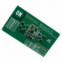
EVAL BOARD FOR NCP1422

NCP1422EVB

Manufacturer Part Number
NCP1422EVB
Description
EVAL BOARD FOR NCP1422
Manufacturer
ON Semiconductor
Datasheets

Specifications of NCP1422EVB

Design Resources
NCP1422 EVB BOM NCP1422EVB Gerber Files NCP1422EVB Schematic
Main Purpose
DC/DC, Step Up
Outputs And Type
1, Non-Isolated
Voltage - Output
3.3 ~ 5 V
Current - Output
800mA
Voltage - Input
2.5V, 3.6V
Regulator Topology
Boost
Frequency - Switching
1.2MHz
Board Type
Fully Populated
Utilized Ic / Part
NCP1422
Lead Free Status / RoHS Status
Lead free / RoHS Compliant
Power - Output
-
Lead Free Status / Rohs Status
Lead free / RoHS Compliant
For Use With/related Products
NCP1422
Other names
NCP1422EVBOS
NCP1422
800 mA Sync−Rect PFM
Step−Up DC−DC Converter
with True−Cutoff and
Ring−Killer
switching converter IC specially designed for battery−operated
hand−held electronic products up to 800 mA loading. It integrates
Sync−Rect to improve efficiency and to eliminate the external
Schottky Diode. High switching frequency (up to 1.2 MHz) allows
for a low profile, small−sized inductor and output capacitor to be
used. When the device is disabled, the internal conduction path from
LX or BAT to OUT is fully blocked and the OUT pin is isolated from
the battery. This True−Cutoff function reduces the shutdown current
to typically only 50 nA. Ring−Killer is also integrated to eliminate
the high−frequency ringing in discontinuous conduction mode. In
addition to the above, Low−Battery Detector, Logic−Controlled
Shutdown, Cycle−by−Cycle Current Limit and Thermal Shutdown
provide value−added features for various battery−operated
applications. With all these functions on, the quiescent supply
current is typically only 8.5 mA. This device is available in the
compact and low profile DFN−10 package.
Features
Typical Applications
© Semiconductor Components Industries, LLC, 2006
February, 2006 − Rev. 3
NCP1422 is a monolithic micropower high−frequency step−up
typically 50 nA
Supply 2.5 mA Loading Current when V
to 3.0−5.0 V or one Lithium−ion cells to 5.0 V
Pb−Free Package is Available*
High Efficiency: 94% for 3.3 V Output at 200 mA from 2.5 V Input
High Switching Frequency, up to 1.2 MHz (not hitting current limit)
Output Current up to 800 mA at V
True−Cutoff Function Reduces Device Shutdown Current to
Anti−Ringing Ring−Killer for Discontinuous Conduction Mode
High Accuracy Reference Output, 1.20 V $1.5% @ 25°C, can
Low Quiescent Current of 8.5 mA
Integrated Low−Battery Detector
Open Drain Low−Battery Detector Output
1.0 V Startup at No Load Guaranteed
Output Voltage from 1.5 V to 5.0 V Adjustable
1.5 A Cycle−by−Cycle Current Limit
Multi−Function Logic−Controlled Shutdown Pin
On Chip Thermal Shutdown with Hysteresis
Personal Digital Assistants (PDA)
Handheld Digital Audio Products
Camcorders and Digital Still Cameras
Hand−held Instruments
Conversion from one to two Alkaline, NiMH, NiCd Battery Cells
White LED Flash for Digital Cameras
88% for 3.3 V Output at 500 mA from 2.5 V Input
IN
= 2.5 V and V
OUT
> 3.3 V
OUT
= 3.3 V
1
NCP1422MNR2
NCP1422MNR2G
†For information on tape and reel specifications,
*For additional information on our Pb−Free strategy
including part orientation and tape sizes, please
refer to our Tape and Reel Packaging Specifications
Brochure, BRD8011/D.
and soldering details, please download the
ON Semiconductor Soldering and Mounting
Techniques Reference Manual, SOLDERRM/D.
Device
1
LBI/EN
1422 = Device Code
A
L
Y
W
G
(Note: Microdot may be in either location)
LBO
REF
NC
ORDERING INFORMATION
FB
= Assembly Location
= Wafer Lot
= Year
= Work Week
= Pb−Free Package
PIN CONNECTIONS
http://onsemi.com
1
2
3
4
5
MN SUFFIX
CASE 485C
(Pb−Free)
(Top View)
Package
DFN−10
DFN−10
DFN−10
DFN−10
Publication Order Number:
3000 Tape & Reel
10
3000 Tape & Reel
9
8
7
6
1
Shipping†
MARKING
DIAGRAM
OUT
NC
LX
GND
BAT
NCP1422/D
ALYWG
1422
G

Related parts for NCP1422EVB

NCP1422EVB Summary of contents

Page 1

... Tape and Reel Packaging Specifications Brochure, BRD8011/D. *For additional information on our Pb−Free strategy and soldering details, please download the ON Semiconductor Soldering and Mounting Techniques Reference Manual, SOLDERRM/D. Publication Order Number: NCP1422/D 1422 ...

Page 2

V Chip Enable − PFM REF Voltage Reference 5 1. LBI/EN − 2 NCP1422 ZLC + − TRUE CUTOFF CONTROL CONTROL LOGIC _ZCUR _TSDON V DD _MSON _MAINSW2ON GND _CEN _PFM ...

Page 3

PIN FUNCTION DESCRIPTIONS Pin Symbol 1 FB Output Voltage Feedback Input. 2 LBI/EN Low−Battery Detector Input and IC Enable. With this pin pulled down below 0.5 V, the device is disabled and enters the shutdown mode. 3 LBO Open−Drain Low−Battery ...

Page 4

ELECTRICAL CHARACTERISTICS otherwise noted.) Characteristic Operating Voltage Output Voltage Range Reference Voltage = 200 nF, T OUT LOAD REF Reference Voltage = ...

Page 5

TYPICAL OPERATING CHARACTERISTICS 1.220 V = 3.3 V OUT 1.210 = OUT = 1 REF T = 25_C A 1.200 1.190 1.180 1 10 ...

Page 6

TYPICAL OPERATING CHARACTERISTICS 3.3 V OUT − OUT T = 25_C A − 100 OUTPUT LOADING CURRENT, I Figure ...

Page 7

TYPICAL OPERATING CHARACTERISTICS = 50 mA 5 OUT LOAD Upper Trace: Output Voltage Ripple, 20 mV/Division Lower Trace: Voltage at Lx pin, 1.0 V/Division Figure 14. Discontinuous ...

Page 8

TYPICAL OPERATING CHARACTERISTICS 100 1 NCP1422 5.0 V OUT OUT T = 25_C ...

Page 9

If the regulator is operating in Continuous Conduction Mode (CCM turned OFF just before M1 is supposed again. If the regulator is operating in Discontinuous Conduction Mode ...

Page 10

Output Voltage Setting A typical application circuit is shown in Figure 23. The output voltage of the converter is determined by the external feedback network comprised of R1 and R2. The relationship is given by OUT ...

Page 11

200 k Shutdown Open Drain Input Low Battery Open Drain Output *Optional Figure 23. Typical Application Schematic for 2 Alkaline Cells Supply Switching mode converter design is considered a complicated process. Selecting the right ...

Page 12

From the previous calculations, you need at least 18. order to achieve the specified ripple level at the conditions stated. Practically, a capacitor that is one level larger is used to accommodate factors not taken into account in ...

Page 13

... BOTTOM VIEW 0.05 C NOTE 3 10X 0.5651 *For additional information on our Pb−Free strategy and soldering details, please download the ON Semiconductor Soldering and Mounting Techniques Reference Manual, SOLDERRM/D. NCP1422 PACKAGE DIMENSIONS DFN10 3mm, 0.5mm Pitch CASE 485C−01 ISSUE EDGE OF PACKAGE L1 ...

Page 14

... Fax: 480−829−7709 or 800−344−3867 Toll Free USA/Canada Email: orderlit@onsemi.com NCP1422 N. American Technical Support: 800−282−9855 Toll Free USA/Canada Japan: ON Semiconductor, Japan Customer Focus Center 2−9−1 Kamimeguro, Meguro−ku, Tokyo, Japan 153−0051 Phone: 81−3−5773−3850 http://onsemi.com 14 ON Semiconductor Website: http://onsemi ...

Related keywords