NCP1422EVB ON Semiconductor, NCP1422EVB Datasheet - Page 11
NCP1422EVB
Manufacturer Part Number
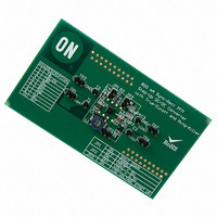
NCP1422EVB
Description
EVAL BOARD FOR NCP1422
Manufacturer
ON Semiconductor
Specifications of NCP1422EVB
Design Resources
NCP1422 EVB BOM NCP1422EVB Gerber Files NCP1422EVB Schematic
Main Purpose
DC/DC, Step Up
Outputs And Type
1, Non-Isolated
Voltage - Output
3.3 ~ 5 V
Current - Output
800mA
Voltage - Input
2.5V, 3.6V
Regulator Topology
Boost
Frequency - Switching
1.2MHz
Board Type
Fully Populated
Utilized Ic / Part
NCP1422
Lead Free Status / RoHS Status
Lead free / RoHS Compliant
Power - Output
-
Lead Free Status / Rohs Status
Lead free / RoHS Compliant
For Use With/related Products
NCP1422
Other names
NCP1422EVBOS


complicated process. Selecting the right inductor and
capacitor values can allow the converter to provide
optimum performance. The following is a simple method
based on the basic first−order equations to estimate the
inductor and capacitor values for NCP1422 to operate in
Continuous Conduction Mode (CCM). The set component
values can be used as a starting point to fine tune the
application circuit performance. Detailed bench testing is
still necessary to get the best performance out of the circuit.
Design Parameters:
Calculate the feedback network:
Calculate the Low Battery Detect divider:
Low Battery
Switching mode converter design is considered a
Open Drain
Open Drain
Shutdown
Output
Input
V
V
I
V
V
Select R2 = 200 k
V
Select R4 = 330 k
R3 + R4
R3 + 300 k
R1 + R2
R1 + 200 k
OUT
IN
OUT
LB
OUT−RIPPLE
LB
V
= 1.8 V to 3.0 V, Typical 2.4 V
= 2.0 V
= 2.0 V
IN
= 500 mA
= 3.3 V
*Optional
R2 200 k
V REF
V OUT
V REF
V LB
1.20 V
= 40 mV
1.20 V
2.0 V
3.3 V
Figure 23. Typical Application Schematic for 2 Alkaline Cells Supply
* 1
* 1
* 1 + 220 k
* 1 + 350 k
p−p
C4
10 p*
at I
OUT
R3
220 k
R4
330 k
GENERAL DESIGN PROCEDURES
TYPICAL APPLICATION CIRCUIT
= 500 mA
R1
350 k
http://onsemi.com
C3
200 nF
NCP1422
FB
LBI/EN
LBO
REF
11
V
maximum I
and calculate the inductor value:
Assume I
power inductor can be calculated as follows:
A standard value of 6.5 mH is selected for initial trial.
calculate the output capacitor value:
V
where t
NCP1422
IN
OUT−RIPPLE
Determine the Steady State Duty Ratio, D, for typical
Determine the average inductor current, I
Determine the peak inductor ripple current, I
Determine the output voltage ripple, V
C OUT u
C OUT u
. The operation is optimized around this point:
C1
22 mF
L +
ON
I LAVG +
GND
RIPPLE−P
2 I RIPPLE*P
OUT
D + 1 *
BAT
= 0.75 mS and ESR
V IN
LX
OUT
V OUT*RIPPLE * I OUT
45 mV * 500 mA
= 40 mV
:
500 mA
t ON
is 20% of I
1 * D
I OUT
V OUT
V IN
V OUT
V IN
P−P
+
+ 500 mA
I OUT
+ 1 * 2.4 V
at I
2.4 V
+
1 * 0.273
0.75 mS
2 (137.6 mA)
LAVG
OUT
33 mF
COUT
1 * D
C2
L
6.5 mH
1
3.3 V
0.05 W
t ON
= 500 mA
. The inductance of the
0.75 mS
= 0.05 ,
+
+ 688 mA
+ 0.273
ESR COUT
+ 18.75 mF
OUT−RIPPLE,
+ 6.5 mH
V
800 mA
OUT
LAVG,
RIPPLE−P,
= 3.3 V
and
at
Related parts for NCP1422EVB
Image
Part Number
Description
Manufacturer
Datasheet
Request
R

Part Number:
Description:
Sync-Rect PFM Step-Up DC-DC Converter
Manufacturer:
ON Semiconductor
Datasheet:
Part Number:
Description:
ON Semiconductor [VOLTAGE REGULATOR]
Manufacturer:
ON Semiconductor
Datasheet:
Part Number:
Description:
357-036-542-201 CARDEDGE 36POS DL .156 BLK LOPRO
Manufacturer:
ON Semiconductor
Datasheet:
Part Number:
Description:
357-036-542-201 CARDEDGE 36POS DL .156 BLK LOPRO
Manufacturer:
ON Semiconductor
Datasheet:
Part Number:
Description:
357-036-542-201 CARDEDGE 36POS DL .156 BLK LOPRO
Manufacturer:
ON Semiconductor
Datasheet:
Part Number:
Description:
357-036-542-201 CARDEDGE 36POS DL .156 BLK LOPRO
Manufacturer:
ON Semiconductor
Datasheet:
Part Number:
Description:
357-036-542-201 CARDEDGE 36POS DL .156 BLK LOPRO
Manufacturer:
ON Semiconductor
Datasheet:
Part Number:
Description:
357-036-542-201 CARDEDGE 36POS DL .156 BLK LOPRO
Manufacturer:
ON Semiconductor
Datasheet:
Part Number:
Description:
357-036-542-201 CARDEDGE 36POS DL .156 BLK LOPRO
Manufacturer:
ON Semiconductor
Datasheet:
Part Number:
Description:
357-036-542-201 CARDEDGE 36POS DL .156 BLK LOPRO
Manufacturer:
ON Semiconductor
Datasheet:
Part Number:
Description:
357-036-542-201 CARDEDGE 36POS DL .156 BLK LOPRO
Manufacturer:
ON Semiconductor
Datasheet:
Part Number:
Description:
357-036-542-201 CARDEDGE 36POS DL .156 BLK LOPRO
Manufacturer:
ON Semiconductor
Datasheet:
Part Number:
Description:
Manufacturer:
ON Semiconductor
Datasheet:
Part Number:
Description:
Manufacturer:
ON Semiconductor
Datasheet: