CDB4385 Cirrus Logic Inc, CDB4385 Datasheet - Page 26
CDB4385
Manufacturer Part Number
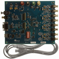
CDB4385
Description
BOARD EVAL FOR CS4385 DAC
Manufacturer
Cirrus Logic Inc
Specifications of CDB4385
Number Of Dac's
8
Number Of Bits
24
Outputs And Type
8, Differential
Sampling Rate (per Second)
192k
Data Interface
Serial
Dac Type
Voltage
Voltage Supply Source
Analog and Digital
Operating Temperature
-40°C ~ 85°C
Utilized Ic / Part
CDB4385
Description/function
Audio D/A
Operating Supply Voltage
5 V
Product
Audio Modules
For Use With/related Products
CS4385
Lead Free Status / RoHS Status
Contains lead / RoHS non-compliant
Lead Free Status / RoHS Status
Lead free / RoHS Compliant, Contains lead / RoHS non-compliant
Other names
598-1154


26
4.3.5
4.4
4.5
Oversampling Modes
The CS4385 operates in one of three oversampling modes based on the input sample rate. Mode selection
is determined by the M4, M3 and M2 pins in Hardware Mode or the FM bits in Software Mode. Single-Speed
mode supports input sample rates up to 50 kHz and uses a 128x oversampling ratio. Double-Speed Mode
supports input sample rates up to 100 kHz and uses an oversampling ratio of 64x. Quad-Speed Mode sup-
ports input sample rates up to 200 kHz and uses an oversampling ratio of 32x.
The auto-speed mode detect feature allows for the automatic selection of speed mode based off of the in-
coming sample rate. This allows the CS4385 to accept a wide range of sample rates with no external inter-
vention necessary. The auto-speed mode detect feature is available in both hardware and Software Mode.
Interpolation Filter
To accommodate the increasingly complex requirements of digital audio systems, the CS4385 incorporates
selectable interpolation filters for each mode of operation. A “fast” and a “slow” roll-off filter is available in
each of Single, Double, and Quad-Speed modes. These filters have been designed to accommodate a va-
riety of musical tastes and styles. The FILT_SEL bit is used to select which filter is used (see the
Plots” on page 48
When in Hardware Mode, only the “fast” roll-off filter is available.
Filter specifications can be found in
SDIN1
LRCK
SCLK
TDM
The TDM serial audio interface format operates in Single-, Double-, or Quad-Speed Mode and will slave
to SCLK at 256 Fs. Data is received most significant bit first on the first SCLK after an LRCK transition
and is valid on the rising edge of SCLK. LRCK identifies the start of a new frame and is equal to the sam-
ple rate, Fs. LRCK is sampled as valid on the rising SCLK edge preceding the most significant bit of the
first data sample and must be held valid for one SCLK period. Each time slot is 32 bits wide, with the valid
data sample left-justified within the time slot with the remaining bits being zero-padded.
LSB
MSB
MSB
DAC_A1
32 clks
Data
for more details).
LSB
LSB
MSB
DAC_B1
32 clks
zero
Figure 19. Format 12 - TDM Mode
LSB
Section
MSB
DAC_A2
32 clks
1, and filter response plots can be found in
LSB
MSB
DAC_B2
32 clks
256 clks
LSB
MSB
DAC_A3
32 clks
LSB
MSB
DAC_B3
32 clks
LSB
MSB
DAC_A4
32 clks
Figures 28
LSB
MSB
CS4385
DAC_B4
32 clks
DS671F2
to 51.
“Filter
LSB
Related parts for CDB4385
Image
Part Number
Description
Manufacturer
Datasheet
Request
R

Part Number:
Description:
Development Kit
Manufacturer:
Cirrus Logic Inc
Datasheet:
Part Number:
Description:
Development Kit
Manufacturer:
Cirrus Logic Inc
Datasheet:


Part Number:
Description:
High-efficiency PFC + Fluorescent Lamp Driver Reference Design
Manufacturer:
Cirrus Logic Inc
Datasheet:
Part Number:
Description:
Development Kit
Manufacturer:
Cirrus Logic Inc
Datasheet:
Part Number:
Description:
Development Kit
Manufacturer:
Cirrus Logic Inc
Datasheet:

Part Number:
Description:
Development Kit
Manufacturer:
Cirrus Logic Inc
Datasheet:
Part Number:
Description:
Development Kit
Manufacturer:
Cirrus Logic Inc
Datasheet:
Part Number:
Description:
Development Kit
Manufacturer:
Cirrus Logic Inc
Datasheet:
Part Number:
Description:
Development Kit
Manufacturer:
Cirrus Logic Inc
Datasheet:

Part Number:
Description:
EVALUATION BOARD FOR CS8427
Manufacturer:
Cirrus Logic Inc
Datasheet:

Part Number:
Description:
BOARD EVAL FOR CS8416 RCVR
Manufacturer:
Cirrus Logic Inc
Datasheet:

Part Number:
Description:
EVALUATION BOARD FOR CS8420
Manufacturer:
Cirrus Logic Inc
Datasheet:

Part Number:
Description:
KIT DEVELOPMENT EP9315 ARM9
Manufacturer:
Cirrus Logic Inc
Datasheet:

Part Number:
Description:
KIT DEVELOPMENT EP9302 ARM9
Manufacturer:
Cirrus Logic Inc
Datasheet: