SSL2102T/DB/FLYB120V,598 NXP Semiconductors, SSL2102T/DB/FLYB120V,598 Datasheet - Page 5
SSL2102T/DB/FLYB120V,598
Manufacturer Part Number
SSL2102T/DB/FLYB120V,598
Description
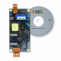
KIT SSL2102 DESIGNER 120V
Manufacturer
NXP Semiconductors
Specifications of SSL2102T/DB/FLYB120V,598
Current - Output / Channel
400mA ~ 1.05A
Outputs And Type
1, Isolated
Voltage - Output
9 ~ 23 V
Features
Dimmable
Voltage - Input
85 ~ 276VAC
Utilized Ic / Part
SSL2102
Duty Cycle (max)
75 %
Mounting Style
SMD/SMT
Switching Frequency
100 KHz
Operating Supply Voltage
8.5 V to 40 V
Supply Current
1.7 A
Maximum Operating Temperature
+ 100 C
Minimum Operating Temperature
- 40 C
Output Power
1.6 W
Package / Case
SOIC-20
Lead Free Status / RoHS Status
Lead free / RoHS Compliant
Lead Free Status / RoHS Status
Lead free / RoHS Compliant, Lead free / RoHS Compliant
Other names
568-4931


NXP Semiconductors
8. Functional description
SSL2102_1
Product data sheet
8.1 Start-up and UnderVoltage LockOut (UVLO)
8.2 Oscillator
The SSL2102 is a LED driver IC that operates directly from the rectified mains.
The SSL2102 uses on-time mode control and frequency control to control the LED
brightness. The BRIGHTNESS and PWMLIMIT input of the IC can be used to control the
LED light output in combination with an external dimmer. The PWMLIMIT input can also
be used for Thermal Lumen Management (TLM) and for precision LED current control.
Initially, the IC is self-supplying from the rectified mains voltage. The IC starts switching as
soon as the voltage on pin V
by the auxiliary winding of the transformer as soon as V
from the line is stopped for high efficiency operation. Alternatively the IC can be supplied
via a bleeder resistor connected to a high voltage.
Remark: The maximum V
If for some reason the auxiliary supply is not sufficient, the high-voltage supply can also
supply the IC. As soon as the voltage on pin V
stops switching and will restart from the rectified mains voltage, if the internal current
delivered is sufficient.
An internal oscillator inside the IC provides the timing for the switching converter logics.
The frequency of the oscillator is set by the external resistors and the capacitor on pin RC
and pin RC2. The external capacitor is charged rapidly to the V
from a new primary stroke, it discharges to the V
exponential, the relative sensitivity of the duty factor to the regulation voltage at low duty
factor is almost equal to the sensitivity at high duty factors. This results in a more constant
gain over the duty factor range compared to Pulse Width Modulated (PWM) systems with
a linear sawtooth oscillator. Stable operation at low duty factors is easily realized. The
frequency of the converter when V
R equals the parallel resistance of both oscillator resistors. C is the capacitor connected at
the RC pin (pin 8).
The BRIGHTNESS input controls the frequency reduction mode.
oscillator switches over from an RC curve with R1//R2 to R1 only. A low BRIGHTNESS
voltage will reduce the switching frequency.
RC
=
------ -
3.5
1
--------- - t
f
1
osc
–
ch
arg
Rev. 01 — 29 June 2009
e
CC
CC
voltage rating of the IC.
passes the V
BRIGHTNESS
CC(startup)
is high can be estimated using
CC
RC(min)
drops below the V
SMPS IC for dimmable LED lighting
level. The supply can be taken over
level. Because the discharge is
CC
is high enough and the supply
RC(max)
Figure 3
CC(UVLO)
level and, starting
SSL2102
© NXP B.V. 2009. All rights reserved.
shows that the
level, the IC
Equation
5 of 21
(1)
1:
Related parts for SSL2102T/DB/FLYB120V,598
Image
Part Number
Description
Manufacturer
Datasheet
Request
R

Part Number:
Description:
KIT SSL2102 DESIGNER 230V
Manufacturer:
NXP Semiconductors
Datasheet:

Part Number:
Description:
NXP Semiconductors designed the LPC2420/2460 microcontroller around a 16-bit/32-bitARM7TDMI-S CPU core with real-time debug interfaces that include both JTAG andembedded trace
Manufacturer:
NXP Semiconductors
Datasheet:

Part Number:
Description:
NXP Semiconductors designed the LPC2458 microcontroller around a 16-bit/32-bitARM7TDMI-S CPU core with real-time debug interfaces that include both JTAG andembedded trace
Manufacturer:
NXP Semiconductors
Datasheet:
Part Number:
Description:
NXP Semiconductors designed the LPC2468 microcontroller around a 16-bit/32-bitARM7TDMI-S CPU core with real-time debug interfaces that include both JTAG andembedded trace
Manufacturer:
NXP Semiconductors
Datasheet:
Part Number:
Description:
NXP Semiconductors designed the LPC2470 microcontroller, powered by theARM7TDMI-S core, to be a highly integrated microcontroller for a wide range ofapplications that require advanced communications and high quality graphic displays
Manufacturer:
NXP Semiconductors
Datasheet:
Part Number:
Description:
NXP Semiconductors designed the LPC2478 microcontroller, powered by theARM7TDMI-S core, to be a highly integrated microcontroller for a wide range ofapplications that require advanced communications and high quality graphic displays
Manufacturer:
NXP Semiconductors
Datasheet:
Part Number:
Description:
The Philips Semiconductors XA (eXtended Architecture) family of 16-bit single-chip microcontrollers is powerful enough to easily handle the requirements of high performance embedded applications, yet inexpensive enough to compete in the market for hi
Manufacturer:
NXP Semiconductors
Datasheet:
Part Number:
Description:
The XA-S3 device is a member of Philips Semiconductors? XA(eXtended Architecture) family of high performance 16-bitsingle-chip microcontrollers
Manufacturer:
NXP Semiconductors
Datasheet:

Part Number:
Description:
The NXP BlueStreak LH75401/LH75411 family consists of two low-cost 16/32-bit System-on-Chip (SoC) devices
Manufacturer:
NXP Semiconductors
Datasheet:
Part Number:
Description:
The NXP LPC3130/3131 combine an 180 MHz ARM926EJ-S CPU core, high-speed USB2
Manufacturer:
NXP Semiconductors
Datasheet:
Part Number:
Description:
The NXP LPC3141 combine a 270 MHz ARM926EJ-S CPU core, High-speed USB 2
Manufacturer:
NXP Semiconductors
Part Number:
Description:
The NXP LPC3143 combine a 270 MHz ARM926EJ-S CPU core, High-speed USB 2
Manufacturer:
NXP Semiconductors

Part Number:
Description:
The NXP LPC3152 combines an 180 MHz ARM926EJ-S CPU core, High-speed USB 2
Manufacturer:
NXP Semiconductors
Part Number:
Description:
The NXP LPC3154 combines an 180 MHz ARM926EJ-S CPU core, High-speed USB 2
Manufacturer:
NXP Semiconductors