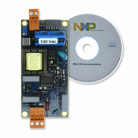
SSL2102T/DB/FLYB120V,598 NXP Semiconductors, SSL2102T/DB/FLYB120V,598 Datasheet - Page 9

SSL2102T/DB/FLYB120V,598
Manufacturer Part Number
SSL2102T/DB/FLYB120V,598
Description
KIT SSL2102 DESIGNER 120V
Manufacturer
NXP Semiconductors
Specifications of SSL2102T/DB/FLYB120V,598
Current - Output / Channel
400mA ~ 1.05A
Outputs And Type
1, Isolated
Voltage - Output
9 ~ 23 V
Features
Dimmable
Voltage - Input
85 ~ 276VAC
Utilized Ic / Part
SSL2102
Duty Cycle (max)
75 %
Mounting Style
SMD/SMT
Switching Frequency
100 KHz
Operating Supply Voltage
8.5 V to 40 V
Supply Current
1.7 A
Maximum Operating Temperature
+ 100 C
Minimum Operating Temperature
- 40 C
Output Power
1.6 W
Package / Case
SOIC-20
Lead Free Status / RoHS Status
Lead free / RoHS Compliant
Lead Free Status / RoHS Status
Lead free / RoHS Compliant, Lead free / RoHS Compliant
Other names
568-4931
NXP Semiconductors
1.
SSL2102_1
Product data sheet
R
SENSE
is the resistor between the SOURCE pin and GND
8.6 Demagnetization
8.7 Overcurrent protection
8.8 Short-winding protection
8.9 Overtemperature protection
The system operates in discontinuous conduction mode if the AUX pin is connected. As
long as the secondary stroke has not ended, the oscillator will not start a new primary
stroke. During the first t
This suppression may be necessary in applications where the transformer has a large
leakage inductance and at low output voltages.
The cycle-by-cycle peak drain current limit circuit uses the external source resistor
R
time t
V
The short-winding protection circuit is also activated after the leading edge blanking time.
If the source voltage exceeds the short-winding protection threshold voltage
V
The short-winding protection also protects in case of a secondary diode short circuit.
Accurate temperature protection is provided in the device. When the junction temperature
exceeds the thermal shut-down temperature, the IC stops switching. During thermal
protection, the IC current is lowered to the start-up current. The IC continues normal
operation as soon as the overtemperature situation has disappeared.
Fig 7.
th(ocp)SOURCE
th(swp)SOURCE
SENSE
leb
(1)
1
. The protection circuit limits the source voltage over the R
to measure the current. The circuit is activated after the leading edge blanking
At N V
Typical phase of drain ringing at switch-on (at
, the IC stops switching. Only a power-on reset will restart normal operation.
and thus limits the primary peak current.
o
= 80 V)
phase
( )
Rev. 01 — 29 June 2009
sup(xfmr_ring)
40
20
20
40
0
0
200
seconds, demagnetization recognition is suppressed.
400
SMPS IC for dimmable LED lighting
600
f (kHz)
014aaa573
800
SENSE
SSL2102
© NXP B.V. 2009. All rights reserved.
resistor to
9 of 21


