MCP1631RD-DCPC1 Microchip Technology, MCP1631RD-DCPC1 Datasheet - Page 17
MCP1631RD-DCPC1
Manufacturer Part Number
MCP1631RD-DCPC1
Description
REF DES BATT CHARG OR LED DRIVER
Manufacturer
Microchip Technology
Datasheets
1.PIC16F616T-ISL.pdf
(214 pages)
2.MCP1631VHVT-330EST.pdf
(34 pages)
3.MCP1631VHVT-330EST.pdf
(32 pages)
Specifications of MCP1631RD-DCPC1
Current - Output / Channel
700mA
Outputs And Type
1, Non-Isolated
Features
Firmware for Li-Ion, NiMH, and NiCd Battery Charger
Voltage - Input
3.5 ~ 16 V
Utilized Ic / Part
MCP1631HV, PIC16F616
Core Chip
MCP1631HV, PIC16F616
Topology
Parallel, Series
Output Current
1A
No. Of Outputs
1
Input Voltage
3.5V To 16V
Dimming Control Type
Analog
Kit Contents
Board
Lead Free Status / RoHS Status
Lead free / RoHS Compliant
Voltage - Output
-
Lead Free Status / Rohs Status
Lead free / RoHS Compliant


© 2009 Microchip Technology Inc.
2.3.1.5
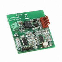
The MCP1631HV Digitally Controlled Programmable Current Source Reference
Design reference board is provided with the LED driver firmware programmed into the
U2 microcontroller.
The reference board package also has compiled firmware
Li-Ion and NiMH/NiCd battery packs. There are two versions of charger firmware. One
is for Li-Ion cells (
(
2.3.1.5.1
To charge a battery pack with the MCP1631HV Digitally Controlled Programmable
Current Source Reference Design, the positive connector of the battery should be
connected to J2-1 (+). The negative terminal of the battery should be connected to
J2-5 (-).
A thermistor referenced to J2-5 (-) should be used for thermal shutdown if the battery
chemistry is NiMH/NiCd. To evaluate a NiMH/NiCd battery charger pack that does not
have an internal thermistor, it is recommended to attach an EPCOS Inc.
P/N: B57500M0103A005 thermistor onto one of the cells of the battery pack. This
thermistor should be connected to J2-4 (+) and J2-5 (-).
For evaluation, all charge parameters can be modified in source code. See the header
file
2.3.1.5.2
The pre-programmed parameters for the battery charge profiles are:
• Li-Ion
• NiMH/NiCd
00234R1-NiMH_NiCd_Charger.hex
- Qualification: Precharge at 200 mA for V
- Constant Current: 1A for 1 Cell, 0.5A for 2 Cells
- Constant Voltage: 4.20V (this value should be calibrated for better accuracy,
- Charge Termination: 70 mA for 1 Cell and 2 Cells
- Overvoltage Detection: Once detected, attempts to restart the charge cycle 5
- Qualification: Precharge at 140 mA for V
- Constant Current: 700 mA for 1 Cell to 4 Cell
- Terminate Fast Charge for -dV/dT or +dT/dt
- Top off Charge Current: 35 mA
- Overvoltage Detection: Once detected, attempts to restart the charge cycle 5
Note:
00234R1.h
see Section 2.3.1.5.4 “Calibrating the Output Voltage for the Li-Ion
Chemistry Profile”)
times. If overvoltage is still present, the charge cycle is aborted and the RED
LED is flashed.
Top off Charge Time: 1 hour
times. If overvoltage is still present, the charge cycle is aborted and the RED
LED is flashed.
MCP1631 PROGRAMMABLE CURRENT SOURCE AS BATTERY
CHARGER
The maximum charge current for the Li-Ion chemistry is programmed and
limited at 1A for a single cell (4.2V) or 500 mA for two cells in series
topology. The pre-programmed maximum charge current for NiMH/NiCd
chemistry is 700 mA.
How to Connect and Charge a Battery with the MCP1631HV Digitally
Controlled Programmable Current Source Reference Design
Charge Profiles
for the pre-processor definitions.
00234R1-LiIon_Charger.hex
Installation and Operation
).
CELL
CELL
) and the other is for NiCd/NIMH cells
< 3.0V
< 0.9V
*.hex
files included for
DS51798A-page 13
Related parts for MCP1631RD-DCPC1
Image
Part Number
Description
Manufacturer
Datasheet
Request
R

Part Number:
Description:
REFERENCE DESIGN MCP1631HV
Manufacturer:
Microchip Technology
Datasheet:

Part Number:
Description:
REFERENCE DESIGN FOR MCP1631HV
Manufacturer:
Microchip Technology
Datasheet:

Part Number:
Description:
Manufacturer:
Microchip Technology Inc.
Datasheet:
Part Number:
Description:
Manufacturer:
Microchip Technology Inc.
Datasheet:
Part Number:
Description:
Manufacturer:
Microchip Technology Inc.
Datasheet:
Part Number:
Description:
Manufacturer:
Microchip Technology Inc.
Datasheet:
Part Number:
Description:
Manufacturer:
Microchip Technology Inc.
Datasheet:
Part Number:
Description:
Manufacturer:
Microchip Technology Inc.
Datasheet:
Part Number:
Description:
Manufacturer:
Microchip Technology Inc.
Datasheet:
Part Number:
Description:
Manufacturer:
Microchip Technology Inc.
Datasheet: