MCP1631RD-DCPC1 Microchip Technology, MCP1631RD-DCPC1 Datasheet - Page 18
MCP1631RD-DCPC1
Manufacturer Part Number
MCP1631RD-DCPC1
Description
REF DES BATT CHARG OR LED DRIVER
Manufacturer
Microchip Technology
Datasheets
1.PIC16F616T-ISL.pdf
(214 pages)
2.MCP1631VHVT-330EST.pdf
(34 pages)
3.MCP1631VHVT-330EST.pdf
(32 pages)
Specifications of MCP1631RD-DCPC1
Current - Output / Channel
700mA
Outputs And Type
1, Non-Isolated
Features
Firmware for Li-Ion, NiMH, and NiCd Battery Charger
Voltage - Input
3.5 ~ 16 V
Utilized Ic / Part
MCP1631HV, PIC16F616
Core Chip
MCP1631HV, PIC16F616
Topology
Parallel, Series
Output Current
1A
No. Of Outputs
1
Input Voltage
3.5V To 16V
Dimming Control Type
Analog
Kit Contents
Board
Lead Free Status / RoHS Status
Lead free / RoHS Compliant
Voltage - Output
-
Lead Free Status / Rohs Status
Lead free / RoHS Compliant


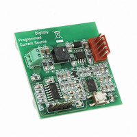
MCP1631HV Digitally Controlled Programmable Current Source Reference Design
DS51798A-page 14
2.3.1.5.3
Follow the instructions in Section 2.3.1.5.1 “How to Connect and Charge a Battery
with the MCP1631HV Digitally Controlled Programmable Current Source
Reference Design” to connect a battery pack at the board. In the Standby (OFF) state,
the GREEN LED will be lit. Push the S1 button to start the charge profile and turn on
the output. The GREEN LED will flash.
If any fault conditions are detected during charging, the RED LED will flash and the
output will automatically turn off. See Table 2-1 to identify the nature of the fault. When
a charge cycle successfully completes, the GREEN LED will be turned ON and the
output will be turned off. The system will stay in a Standby (OFF) state until the next
button push.
At any moment, the charging can be stopped by pressing and holding the push button
until the RED LED turns on.
The default calibration value for the Li-Ion pack is 4.2V. For better accuracy, the output
voltage should be calibrated before starting a charge cycle. See
Section 2.3.1.5.4 “Calibrating the Output Voltage for the Li-Ion Chemistry Profile”
for instructions.
2.3.1.5.4
Prior to the first Li-Ion charging cycle, it is recommended to calibrate the charger
termination voltage for better accuracy. Connect a 12V power supply to the J1
connector. Select another power supply for the calibration voltage and set it to the
desired termination voltage between 3.9V and 4.20V. Connect the calibration power
supply to the J2 connector. Connect the positive lead to J2-1 and the negative lead to
J2-5.
1. Press S1 to turn on the board.
2. Wait for the GREEN LED to light. If it does not light, check for faults.
3. When the GREEN LED is lit, press and hold down S1 for 2 seconds until the
4. The calibration power supply can now be removed from the J2 output connector.
YELLOW LED (both green and red LEDs) is lit. The YELLOW status indicator
signals the calibration is complete.
How the MCP1631HV Digitally Controlled Programmable Current Source
Reference Design Operates in Charger Mode
Calibrating the Output Voltage for the Li-Ion Chemistry Profile
© 2009 Microchip Technology Inc.
Related parts for MCP1631RD-DCPC1
Image
Part Number
Description
Manufacturer
Datasheet
Request
R

Part Number:
Description:
REFERENCE DESIGN MCP1631HV
Manufacturer:
Microchip Technology
Datasheet:

Part Number:
Description:
REFERENCE DESIGN FOR MCP1631HV
Manufacturer:
Microchip Technology
Datasheet:

Part Number:
Description:
Manufacturer:
Microchip Technology Inc.
Datasheet:
Part Number:
Description:
Manufacturer:
Microchip Technology Inc.
Datasheet:
Part Number:
Description:
Manufacturer:
Microchip Technology Inc.
Datasheet:
Part Number:
Description:
Manufacturer:
Microchip Technology Inc.
Datasheet:
Part Number:
Description:
Manufacturer:
Microchip Technology Inc.
Datasheet:
Part Number:
Description:
Manufacturer:
Microchip Technology Inc.
Datasheet:
Part Number:
Description:
Manufacturer:
Microchip Technology Inc.
Datasheet:
Part Number:
Description:
Manufacturer:
Microchip Technology Inc.
Datasheet: