EVALED7706 STMicroelectronics, EVALED7706 Datasheet - Page 33
EVALED7706
Manufacturer Part Number
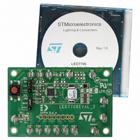
EVALED7706
Description
EVALUATION BOARD FOR LED7706
Manufacturer
STMicroelectronics
Datasheet
1.LED7706TR.pdf
(46 pages)
Specifications of EVALED7706
Current - Output / Channel
30mA
Outputs And Type
6, Non-Isolated
Voltage - Output
36 V
Features
Dimmable, Extra 5V Output
Voltage - Input
4.5 ~ 36 V
Utilized Ic / Part
LED7706
Lead Free Status / RoHS Status
Lead free / RoHS Compliant
Other names
497-6445
Available stocks
Company
Part Number
Manufacturer
Quantity
Price


LED7706
6.4.5
6.4.6
Equation 37
The worst case for the output voltage ripple is when input voltage is lower (V
A simple way to select the C
In order to affect as less as possible the current generators, it would be better to fix the
maximum ripple lower than the typical voltage across the generators.
For example considering ΔV
leading generator), the required capacitance is:
Equation 38
A margin from the calculated value should be taken into account because of the
capacitance drop due to the applied voltage when MLCCs are used.
A 4.7 µF MLCC can be a good choice for this application (two 2.2 μF MLCC in parallel can
be also a good solution).
In case a dimming duty cycle different from 100 % is used, a further contribution to the
capacitor discharge (during the off time of the dimming cycle) should be considered.
Input capacitor choice
The input capacitor of a boost converter is less critical than the output capacitor, due to the
fact that the inductor is in series with the input, and hence, the input current waveform is
continuous.
A low ESR capacitor is always recommended.
A capacitor of 10 µF is tentatively a good choice for most of the applications.
Over-voltage protection divider setting
The over-voltage protection (OVP) divider provides a partition of the output voltage to the
OVSEL pin. The OVP divider setting not only fixes the OVP threshold, but also the open-
channel detection threshold (95 % of the OVP threshold).
The proper OVP divider setting can be calculated by the equation (3):
Equation 39
where V
the maximum V
OUT, MAX
F
is the maximum output voltage considering the worst case (all LEDs with
= V
D
F,max
2
=
= 3.7 V on the same row):
C
2
OUT
OUT
R
R
OUT
⋅
F
0
2
SW
⋅
=
lower than 80 mV (i.e. the 20 % of the voltage across the
value is fixing a maximum voltage ripple.
(
M
>
R
⋅
L
(
−
1
I
, L
⋅
⋅
1
peak
M
V (
)
2
OUT
Δ ⋅
=
−
⎧
⎨
⎩
V
,
I
. 0
MAX
OUT
OUT
. 0
263
. 1
23
,
max
)
+
234
⋅
T
2
OFF
V
@
@
V
−
. 1
=
V
V
234
. 2
IN
IN
,
,
02
max
min
) V
μ
F
=
=
9
14
6 .
Application information
4 .
V
V
IN,min
= 9.6 V).
33/46
Related parts for EVALED7706
Image
Part Number
Description
Manufacturer
Datasheet
Request
R

Part Number:
Description:
ENERCHIP CC EVAL KIT
Manufacturer:
Cymbet Corporation
Datasheet:

Part Number:
Description:
BOARD EVAL FOR AD976
Manufacturer:
Analog Devices Inc
Datasheet:

Part Number:
Description:
BOARD EVAL FOR ADXL345
Manufacturer:
Analog Devices Inc
Datasheet:

Part Number:
Description:
ENERCHIP CC SEH EVAL KIT
Manufacturer:
Cymbet Corporation
Datasheet:

Part Number:
Description:
ENERCHIP EP ENERGY HARVEST EVAL
Manufacturer:
Cymbet Corporation
Datasheet:

Part Number:
Description:
EVAL BOARD FOR TW6864-LB2-GR
Manufacturer:
Intersil
Datasheet:
Part Number:
Description:
EVAL BOARD FOR TW8816-LB3-GR
Manufacturer:
Intersil
Datasheet:
Part Number:
Description:
EVAL BOARD FOR TW8817-TA3-GRS
Manufacturer:
Intersil
Datasheet:

Part Number:
Description:
EVALUATION MODULE FOR ADUM4160
Manufacturer:
Analog Devices Inc
Datasheet:

Part Number:
Description:
BOARD EVALUATION ADCMP581BCP
Manufacturer:
Analog Devices Inc
Datasheet:
Part Number:
Description:
BOARD EVALUATION ADM1041
Manufacturer:
Analog Devices Inc
Datasheet:

Part Number:
Description:
EVAL BOARD FOR STM32F107VCT
Manufacturer:
STMicroelectronics
Datasheet:
Part Number:
Description:
BOARD EVAL FOR AD1954
Manufacturer:
Analog Devices Inc
Datasheet:
Part Number:
Description:
BOARD EVAL FOR AD1955
Manufacturer:
Analog Devices Inc
Datasheet:

Part Number:
Description:
BOARD EVAL FOR AD7655
Manufacturer:
Analog Devices Inc
Datasheet: