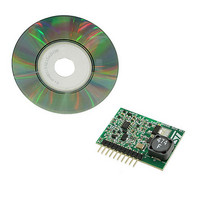
EVL6562A-LED STMicroelectronics, EVL6562A-LED Datasheet - Page 22

EVL6562A-LED
Manufacturer Part Number
EVL6562A-LED
Description
EVALUATION MODULE L6562A
Manufacturer
STMicroelectronics
Type
Power Factor Correctionr
Specifications of EVL6562A-LED
Current - Output / Channel
350mA
Outputs And Type
1, Non-Isolated
Features
Dimmable
Voltage - Input
48V
Utilized Ic / Part
L6562A
Input Voltage
48 V
Product
Power Management Modules
Lead Free Status / RoHS Status
Lead free / RoHS Compliant
Voltage - Output
-
Lead Free Status / Rohs Status
Lead free / RoHS Compliant
For Use With/related Products
L6562A
Other names
497-10420
Available stocks
Company
Part Number
Manufacturer
Quantity
Price
2.8
22/32
Circuit description
Open-/short-circuit protection
As indicated, one of the requirements is that the module can sustain open and short circuits
indefinitely and restart the correct functionality as soon as the fault is removed.
From the "open circuit" point of view the module is intrinsically safe: if the load is
disconnected, no current runs through the sense resistor and the controller drives the power
MOSFET transistor in conduction and pin 10 of the J1 connector to ground. Whenever the
load is reconnected, the current restarts to flow and normal operation is resumed.
The short-circuit condition is more critical. At the end of the toff delay, the power MOSFET is
turned on, the current starts to flow and charges the inductor, and the voltage on the sense
resistor quickly reaches the threshold level. However, because of the controller’s internal
delay (175 nS nom.) the power MOSFET does not shut down immediately; as such, a
minimal amount of energy is still transferred to the inductor, but during the toff time – since
the load is a short-circuit – this energy is NOT dissipated.
The result is that the load current rises abnormally, leading to catastrophic failure unless the
cycle is blocked.
For this reason the circuit outlined in
Figure 22. Short-circuit protection
In normal conditions the voltage developed across the sense resistor is not sufficient to turn
on Q3. The INV pin of the controller is then at:
Equation 50
On the other hand, in the case of a short-circuit, the load current increases until Q3 goes in
conduction, C5 is discharged and the INV pin goes to:
Equation 51
The controller then shuts down, the power MOSFET stops conducting, the inductor
discharges and the load current decays to zero. Since no current flows through the sense
(
Q
3
_
Vce
(
Vcc
_
sat
* )
⎛
⎜
⎝
* )
R
6
⎛
⎜
⎝
R
+
7
R
R
R
+
9
7
9
Doc ID 15679 Rev 1
R
+
9
R
⎞
⎟
⎠
9
=
⎞
⎟
⎠
Figure 22
(
=
. 0
(
18
25
V
V
* )
* )
⎛
⎜ ⎜
⎝
⎛
⎜ ⎜
⎝
has been introduced.
(
(
220
33
K
22
K
+
K
+
22
22
33
) K
K
K
⎞
⎟ ⎟
⎠
+
=
22
(
. 0
) K
25
⎞
⎟ ⎟
⎠
* )
=
. 1
0 (
44
4 .
V )
V
=
0
1 .
V
AN2983


