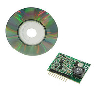
EVL6562A-LED STMicroelectronics, EVL6562A-LED Datasheet - Page 8

EVL6562A-LED
Manufacturer Part Number
EVL6562A-LED
Description
EVALUATION MODULE L6562A
Manufacturer
STMicroelectronics
Type
Power Factor Correctionr
Specifications of EVL6562A-LED
Current - Output / Channel
350mA
Outputs And Type
1, Non-Isolated
Features
Dimmable
Voltage - Input
48V
Utilized Ic / Part
L6562A
Input Voltage
48 V
Product
Power Management Modules
Lead Free Status / RoHS Status
Lead free / RoHS Compliant
Voltage - Output
-
Lead Free Status / Rohs Status
Lead free / RoHS Compliant
For Use With/related Products
L6562A
Other names
497-10420
Available stocks
Company
Part Number
Manufacturer
Quantity
Price
2.2
8/32
Circuit description
Equation 5
Equation 6
L6562A controller
The L6562A is used in a "fixed off time" and "peak current mode" topology.
represents the controller with its main functional blocks, the FOT_Delay circuitry and the
power section.
Figure 6.
At power-on, the "starter" sets the flip-flop, whose output (Q) goes high activating the gate
driver (GD).
The power MOSFET transistor is turned on and the load current (I_Led) flows through the
LED diodes, inductor, power MOSFET transistor and sense resistor.
The load current develops a voltage on the sense resistor: V
This voltage is applied to the CS input of the controller where it is compared to the reference
voltage Vth = 1.08 V (nom.)
When Vs becomes higher than Vth, the comparator's output goes high, activating the reset
input of the FF.
The FF Q output is set to low and the gate driver output voltage goes to gnd.
The power MOSFET is turned off, Vs goes to zero and the I_Led current decreases, flowing
through the LEDs, inductor and Flywheel diode.
Controller diagram
_ I
Led
_ I
Doc ID 15679 Rev 1
Led
_
avg
_
avg
=
_ I
=
Led
_ I
Led
_
pk
_
−
pk
1
2
−
⎡
⎢
⎣
1
VLed
2
L
_ I
S
rip
⎤
⎥
⎦
= I_Led * RSense.
∗
toff
Figure 6
AN2983


