STEVAL-ILL027V1 STMicroelectronics, STEVAL-ILL027V1 Datasheet
STEVAL-ILL027V1
Specifications of STEVAL-ILL027V1


Related parts for STEVAL-ILL027V1


STEVAL-ILL027V1 Summary of contents
Page 1
Introduction With the rapid development of high brightness LEDs, SSL (solid state lighting) has begun to move from being a niche market to penetrating residential markets. There is a large potential market for the residential application of SSL, and CFL ...
Page 2
... Contents Contents 1 Circuit design . . . . . . . . . . . . . . . . . . . . . . . . . . . . . . . . . . . . . . . . . . . . . . 5 2 STEVAL-ILL027V1 demonstration board . . . . . . . . . . . . . . . . . . . . . . . . 13 3 STEVAL-ILL027V2 demonstration board . . . . . . . . . . . . . . . . . . . . . . . . 14 3.1 Schematic diagram . . . . . . . . . . . . . . . . . . . . . . . . . . . . . . . . . . . . . . . . . . 14 3.2 BOM for the STEVAL-ILL027V2 demonstration board . . . . . . . . . . . . . . . 15 3.3 STEVAL-ILL027V2 description for EU voltage range . . . . . . . . . . . . . . . . 15 3.4 Measurement . . . . . . . . . . . . . . . . . . . . . . . . . . . . . . . . . . . . . . . . . . . . . . 17 4 Conclusion . . . . . . . . . . . . . . . . . . . . . . . . . . . . . . . . . . . . . . . . . . . . . . . . 22 5 Reference . . . . . . . . . . . . . . . . . . . . . . . . . . . . . . . . . . . . . . . . . . . . . . . . . 22 6 Revision history . . . . . . . . . . . . . . . . . . . . . . . . . . . . . . . . . . . . . . . . . . . 22 2/23 Doc ID 16815 Rev 2 ...
Page 3
... AN3111 List of tables Table 1. Bill of material for the STEVAL-ILL027V1 Table 2. Bill of material for the STEVAL-ILL027V2 Table 3. Document revision history . . . . . . . . . . . . . . . . . . . . . . . . . . . . . . . . . . . . . . . . . . . . . . . . . 22 Doc ID 16815 Rev 2 List of tables 3/23 ...
Page 4
... Figure 8. Switching waveform of MOSFET Q1: conclusions when Vout > Vin . . . . . . . . . . . . . . . . . 11 Figure 9. Switching waveform of MOSFET Q1: conclusions when Vout < Vin . . . . . . . . . . . . . . . . . 11 Figure 10. STEVAL-ILL027V2 schematic diagram . . . . . . . . . . . . . . . . . . . . . . . . . . . . . . . . . . . . . . . 14 Figure 11. Output LED current and voltage for input voltage 230 Figure 12. Output LED current and voltage for input voltage 180 Figure 13. ...
Page 5
AN3111 1 Circuit design The L6562A is a current mode PFC controller operating in transition mode (boundary mode between CCM and DCM). Its linear multiplier enables the converter to shape the AC input current waveform following the input voltage. The ...
Page 6
Circuit design Figure 3. Schematic diagram of the single-stage LED driver 6/23 Doc ID 16815 Rev 2 AN3111 ...
Page 7
AN3111 The proposed circuit runs at constant peak current. The current sensing voltage is set for 1 V, which is the clamping voltage of the current sensing comparator of the L6562A. The voltage of the LED string is sensed on ...
Page 8
Circuit design The frequency is: Equation 5 The switching frequency varies during the line cycle, which is good for EMI. The max. frequency occurs at peak input voltage: Equation 6 The input power is: Equation 7 Equation 8 The integration ...
Page 9
AN3111 From Equation have: Equation Ω current sensing resistor can be used in the application. To better handle the high current, two SMT 2 Ω resistors are implemented. Operating principles: The operation of the ...
Page 10
Circuit design The efficiency of the circuit is 88%, and the power factor is 0.85. Key waveforms are shown in the figures below. Figure 5 shows the envelope of inductor current and input signal at the MULT pin. Figure 5. ...
Page 11
AN3111 Figure 7. LED voltage and LED current and show the MOSFET switching waveforms. When the input line voltage is lower Figure 8 9 than the output voltage, zero voltage turn-on is achieved. When the input voltage is higher than ...
Page 12
Circuit design Equation 13 2. Short-circuit If the load is shorted, the reflected voltage is zero, and the V Therefore automatically protected from short-circuits. In both fault conditions, the input power is less than 0.5 W. 12/23 Vovp ...
Page 13
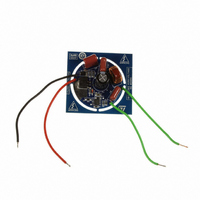
... AN3111 2 STEVAL-ILL027V1 demonstration board Table 1. Bill of material for the STEVAL-ILL027V1 Reference Part description / part number C1 82 µF / 100 µ 0.1 µ C8, C10 0.27 µF/250 V ECQ-E2274KF C9 0.68 µF/250 V ECQ-E2684KB D1 1 A/600 V diode bridge DF06S D3 1N4148WS D7, D8 STTH1L06A choke 744821120 Q1 STD5NM50 R3 10 kΩ ...
Page 14
... STEVAL-ILL027V2 demonstration board 3 STEVAL-ILL027V2 demonstration board An original demonstration board (STEVAL-ILL027V1) was redesigned in order to demonstrate this design concept also for the EU input voltage range. In fact, it means that the board can operate with the input voltage between 188 V and 265 V AC. The LED constant current is again set to 350 mA using the same output LED power 18 W ...
Page 15
... In order to supply the STEVAL-ILL027V2 from the EU voltage range necessary to change the input foil capacitors C8, C9, and C10, because their maximum voltage is only 250 V DC (STEVAL-ILL027V1). The capacitors C8 and C10 were replaced by capacitor 470 nF / 305 V AC. Due to their size, the PCB layout was redesigned in order to fit the bigger ...
Page 16
... For this kind of topology the switching losses are higher for higher input voltage and therefore the power MOSFET with better current capability is selected for the input voltage 230 V AC. The STD11NM50N power MOSFET is used for the STEVAL-ILL027V2 demonstration board. Maximum reverse voltage on diode D7 is also 445 V, when the power MOSFET is ON. ...
Page 17
... V. The LED current vs. input voltage characteristic is demonstrated in Figure 18 . Figure 11. Output LED current and voltage for input voltage 230 Figure 12. Output LED current and voltage for input voltage 180 show output LED current and voltage waveforms. The LED current is Doc ID 16815 Rev 2 STEVAL-ILL027V2 demonstration board 17/23 ...
Page 18
... STEVAL-ILL027V2 demonstration board Figure 13. Output LED current and voltage for input voltage 260 case the output LEDs are disconnected, STEVAL-ILL027V2 has designed an open load protection. Figure 14 As can be seen, output voltage is regulated Figure 14. Open load measurement Figure 15 shows short-circuit protection. As soon as the voltage on the V ...
Page 19
... R12 and R16 and the cycle is repeated. Figure 15. Short-circuit measurement The STEVAL-ILL027V2 demonstration board is also tested for EMI behavior. The EN55015 (CISPR15) standard describes limits and methods for the measurement of radio disturbance characteristics of electrical lighting and similar equipment. STEVAL-ILL027V2 fulfills this standard, as demonstrated in Figure 16 ...
Page 20
... STEVAL-ILL027V2 demonstration board Figure 17. EMI measurement - detector quasi-peak Figure 18 shows LED current for the input voltage between 180 and 260 V AC. Minimum measured LED current is 318 mA for 180 V and maximum measured LED current is 358 mA for 260 V. Figure 19 input voltage 230 V AC. ...
Page 21
... AN3111 Figure 19. Efficiency vs. input voltage Figure 20. LED current vs. LED number STEVAL-ILL027V2 demonstration board Doc ID 16815 Rev 2 21/23 ...
Page 22
... SSL Revision 1 Initial release. Corrected Figure 4, section “2 single-stage offline LED driver for EU voltage range” to section “2.5 STEVAL-ILL027V1 2 modifications for EU voltage range” replaced by ILL027V2 demonstration design and Section 2: STEVAL-ILL027V1 demonstration Doc ID 16815 Rev 2 Changes Section 3: STEVAL- ...
Page 23
... AN3111 Information in this document is provided solely in connection with ST products. STMicroelectronics NV and its subsidiaries (“ST”) reserve the right to make changes, corrections, modifications or improvements, to this document, and the products and services described herein at any time, without notice. All ST products are sold pursuant to ST’s terms and conditions of sale. ...