STEVAL-ILL014V1 STMicroelectronics, STEVAL-ILL014V1 Datasheet - Page 10
STEVAL-ILL014V1
Manufacturer Part Number
STEVAL-ILL014V1
Description
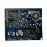
BOARD EVAL BASED ON STCS1
Manufacturer
STMicroelectronics
Specifications of STEVAL-ILL014V1
Design Resources
STEVAL-ILL014V1 Gerber Files STEVAL-ILL014V1 Schematic STEVAL-ILL014V1 Bill of Materials
Current - Output / Channel
1.5A
Outputs And Type
1, Non-Isolated
Features
Dimmable
Voltage - Input
4.5 ~ 40V
Utilized Ic / Part
STCS1
Description/function
LED Driver Evaluation Module
Product
Display Modules
Core Chip
STCS1
Output Current
1.5A
Dimming Control Type
PWM
Development Tool Type
Hardware - Eval/Demo Board
Mcu Supported Families
STCS1
Rohs Compliant
Yes
Lead Free Status / RoHS Status
Lead free / RoHS Compliant
Voltage - Output
-
Lead Free Status / Rohs Status
Lead free / RoHS Compliant
For Use With/related Products
STCS1
Other names
497-8264
Available stocks
Company
Part Number
Manufacturer
Quantity
Price
Company:

Part Number:
STEVAL-ILL014V1
Manufacturer:
STMicroelectronics
Quantity:
1


8
8.1
Figure 11. Reverse polarity condition
8.2
10/17
Application information
Reverse polarity protection
STCS1 must be protected from reverse connection of the supply voltage. Since the current
sunk from V
protect the chip. Care must be taken for the whole application circuit, especially for the
LEDs, in fact, in case a negative voltage is applied between V
voltage will be applied to the LED string that must have a total breakdown voltage higher
than the negative applied voltage in order to avoid any damage.
Thermal considerations
The STCS1 is able to control a LED current up to 1.5 A and able to sustain a voltage on the
drain pin up to 40 V. Those operating conditions are however limited by thermal constraints,
the thermal resistances shown in the
particular R
board under the pad. DFN8 and PowerSO-8 have an exposed die attach pad which
enhances the thermal conductivity enabling high power application.
The power dissipation in the device can be calculated as follow:
P
basing on this and on the thermal resistance and ambient temperature, the junction
temperature can be calculated as:
T
A typical application could be:
J
D
= R
– Input Voltage: 12 V;
– 3 white LEDs with an typical V
– LEDs current: 500 mA;
= (V
thJA
DRAIN
x P
thJA
CC
- V
D
pin is in the range of 450 µA a small diode connected to V
depends on the copper area and the number of layers of the printed circuit
+ T
FB
V
V
A
) x I
IN
IN
LED
BAT46
BAT46
or similar
or similar
+
+
+ (V
CC
x I
CC
F
Table 4: Thermal data
= 3.6 V;
PWM
PWM
EN
EN
)
V
V
DISC
DISC
CC
CC
GND
GND
DRAIN
DRAIN
FB
FB
section are the typical ones, in
IN
and GND, a negative
CC
is able to
Related parts for STEVAL-ILL014V1
Image
Part Number
Description
Manufacturer
Datasheet
Request
R

Part Number:
Description:
BOARD EVAL FOR MEMS SENSORS
Manufacturer:
STMicroelectronics
Datasheet:

Part Number:
Description:
KIT DEV STARTER ST10F276Z5
Manufacturer:
STMicroelectronics
Datasheet:

Part Number:
Description:
BOARD EVAL HDMI $ VIDEO SWITCH
Manufacturer:
STMicroelectronics
Datasheet:

Part Number:
Description:
BOARD DEMO ACCELEROMETER DIL24
Manufacturer:
STMicroelectronics
Datasheet:

Part Number:
Description:
BOARD STLM75/STDS75/ST72F651
Manufacturer:
STMicroelectronics
Datasheet:

Part Number:
Description:
EVAL BOARD 3AXIS MEMS ACCELLRMTR
Manufacturer:
STMicroelectronics
Datasheet:

Part Number:
Description:
BOARD EVAL 8BIT MICRO + TDE1708
Manufacturer:
STMicroelectronics
Datasheet:

Part Number:
Description:
EVAL BOARD A/D TS4657
Manufacturer:
STMicroelectronics
Datasheet:

Part Number:
Description:
BOARD ADAPTER 20DIP LIS3LV02DL
Manufacturer:
STMicroelectronics
Datasheet:

Part Number:
Description:
BOARD DEMO STM8S207R6/LIS331DLH
Manufacturer:
STMicroelectronics
Datasheet:

Part Number:
Description:
STMicroelectronics [RIPPLE-CARRY BINARY COUNTER/DIVIDERS]
Manufacturer:
STMicroelectronics
Datasheet:
Part Number:
Description:
STMicroelectronics [LIQUID-CRYSTAL DISPLAY DRIVERS]
Manufacturer:
STMicroelectronics
Datasheet:
Part Number:
Description:
BOARD EVAL FOR MEMS SENSORS
Manufacturer:
STMicroelectronics
Datasheet: