LM3405XEVAL National Semiconductor, LM3405XEVAL Datasheet - Page 8
LM3405XEVAL
Manufacturer Part Number
LM3405XEVAL
Description
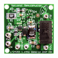
BOARD EVALUATION LM3405X
Manufacturer
National Semiconductor
Series
PowerWise®r
Specifications of LM3405XEVAL
Current - Output / Channel
1A
Outputs And Type
1, Non-Isolated
Voltage - Output
0.2 ~ 13.5 V
Features
Dimmable
Voltage - Input
3 ~ 15V
Utilized Ic / Part
LM3405
Kit Contents
Board, Datasheet
Svhc
No SVHC (15-Dec-2010)
Kit Features
Cycle-by-Cycle Current Limit,
Rohs Compliant
No
Lead Free Status / RoHS Status
Contains lead / RoHS non-compliant


www.national.com
The fourth method can be used in an application which has
an external low voltage rail, V
D2 from V
Again for best performance, ensure that the gate drive volt-
age, V
SETTING THE LED CURRENT
LM3405 is a constant current buck regulator. The LEDs are
connected between V
Application Circuit. The FB pin is at 0.205V in regulation and
therefore the LED current I
from FB to ground by the following equation:
I
therefore R1 minimum must be approximately 0.2Ω. I
also be kept above 200mA for stable operation, and therefore
R1 maximum must be approximately 1Ω. If average LED cur-
rents less than 200mA are desired, the EN/DIM pin can be
used for PWM dimming. See LED PWM DIMMING section.
OUTPUT VOLTAGE
The output voltage is primarily determined by the number of
LEDs (n) connected from V
can be written as :
where V
current level (see LED manufacturer datasheet for forward
characteristics curve).
ENABLE MODE / SHUTDOWN MODE
The LM3405 has both enable and shutdown modes that are
controlled by the EN/DIM pin. Connecting a voltage source
greater than 1.8V to the EN/DIM pin enables the operation of
LM3405, while reducing this voltage below 0.4V places the
part in a low quiescent current (0.3µA typical) shutdown
mode. There is no internal pull-up on EN/DIM pin, therefore
an external signal is required to initiate switching. Do not allow
this pin to float or rise to 0.3V above V
that when the EN/DIM pin voltage rises above 1.8V while the
input voltage is greater than UVLO, there is a finite delay be-
fore switching starts. During this delay the LM3405 will go
through a power on reset state after which the internal soft-
start process commences. The soft-start process limits the
inrush current and brings up the LED current (I
and controlled fashion. The total combined duration of the
power on reset delay, soft-start delay and the delay to fully
establish the LED current is in the order of 100µs (refer to
Figure 11).
The simplest way to enable the operation of LM3405 is to
connect the EN/DIM pin to V
LM3405 whenever the input voltage is applied. However,
when an input voltage of slow rise time is used to power the
application and if both the input voltage and the output voltage
are not fully established before the soft-start time elapses, the
control circuit will command maximum duty cycle operation of
the internal power switch to bring up the output voltage rapid-
ly. When the feedback pin voltage exceeds 0.205V, the duty
cycle will have to reduce from the maximum value according-
ly, to maintain regulation. It takes a finite amount of time for
this reduction of duty cycle and this will result in a spike in LED
current for a short duration as shown in Figure 6. In applica-
tions where this LED current overshoot is undesirable, EN/
DIM pin voltage can be delayed with respect to V
V
the enable threshold. This delay can be implemented by a
simple R
F
IN
should not exceed the 1A current capability of LM3405 and
is fully established before the EN/DIM pin voltage reaches
EXT
F
a
-C
- V
is the forward voltage of one LED at the set LED
EXT
a
D2
, independent of V
network as shown in Figure 7. The effect of
+ V
V
D1
OUT
, falls in the range of 2.5V to 5.5V.
OUT
I
= ((n x V
F
and FB pin as shown in the Typical
= V
F
OUT
is set by V
EXT
FB
IN
to FB pin and therefore V
which allows self start-up of
. C3 can be charged through
/ R1
IN
F
) + V
and V
FB
FB
IN
. It should be noted
)
and the resistor R1
OUT
voltage levels.
F
) in a smooth
IN
such that
F
should
OUT
8
adding this R
Figure 8. For a fast rising input voltage (200µs for example),
there is no need to delay the EN/DIM signal since soft-start
can smoothly bring up the LED current as shown in Figure
9.
FIGURE 8. Startup Response to V
FIGURE 6. Startup Response to V
FIGURE 7. EN/DIM delayed with respect to V
a
-C
a
network on the LED current is shown in
IN
IN
with EN/DIM delayed
with 5ms rise time
20178977
20178976
IN
20178998
Related parts for LM3405XEVAL
Image
Part Number
Description
Manufacturer
Datasheet
Request
R

Part Number:
Description:
Precision Fahrenheit Temperature Sensors
Manufacturer:
National Semiconductor
Part Number:
Description:
National Semiconductor [8-Bit D/A Converter]
Manufacturer:
National Semiconductor
Datasheet:
Part Number:
Description:
National Semiconductor [Media Coprocessor]
Manufacturer:
National Semiconductor
Datasheet:
Part Number:
Description:
Digitally Controlled Tone and Volume Circuit with Stereo Audio Power Amplifier, Microphone Preamp Stage and National 3D Sound
Manufacturer:
National Semiconductor
Datasheet:
Part Number:
Description:
Digitally Controlled Tone and Volume Circuit with Stereo Audio Power Amplifier, Microphone Preamp Stage and National 3D Sound
Manufacturer:
National Semiconductor
Datasheet:
Part Number:
Description:
AC97 Rev 2 Codec with Sample Rate Conversion and National 3D Sound
Manufacturer:
National Semiconductor
Part Number:
Description:
Manufacturer:
National Semiconductor
Datasheet:
Part Number:
Description:
Manufacturer:
National Semiconductor
Datasheet:
Part Number:
Description:
General Purpose, Low Voltage, Low Power, Rail-to-Rail Output Operational Amplifiers
Manufacturer:
National Semiconductor
Datasheet:
Part Number:
Description:
8-bit 20 MSPS flash A/D converter.
Manufacturer:
National Semiconductor
Datasheet:
Part Number:
Description:
Low Noise Quad Operational Amplifier
Manufacturer:
National Semiconductor
Datasheet:
Part Number:
Description:
Quad Differential Line Receivers
Manufacturer:
National Semiconductor
Datasheet:
Part Number:
Description:
Quad High Speed Trapezoidal? Bus Transceiver
Manufacturer:
National Semiconductor
Datasheet: