LM27961TLEV National Semiconductor, LM27961TLEV Datasheet - Page 10
LM27961TLEV
Manufacturer Part Number
LM27961TLEV
Description
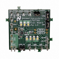
BOARD EVALUATION LM27961TL
Manufacturer
National Semiconductor
Datasheet
1.LM27961TLNOPB.pdf
(13 pages)
Specifications of LM27961TLEV
Current - Output / Channel
20mA
Outputs And Type
7, Non-Isolated
Voltage - Output
4 V
Features
Charge Pump
Voltage - Input
2.7 ~ 5.5V
Utilized Ic / Part
LM27961
Lead Free Status / RoHS Status
Not applicable / Not applicable


www.national.com
Circuit Description
anode outputs and a group of 3 common cathode outputs.
There is an ON/OFF control pin for each group (ENA and
ENB).
The DC current through the LEDs is programmed with an
external resistor. Changing currents on-the-fly can be
achieved with the use of digital pulse (PWM) signals.
ENABLE PINS: ENA, ENB
The LM27961 has 2 enable pins. Both are active-high logic
(HIGH = ON). There are internal pull-down resistors (300kΩ
typ.) that are connected internally between each of the en-
able pins and GND.
ENA and ENB can both enable and disable the part. When
the voltage on both pins are low (
shutdown mode. All internal circuitry is OFF and the part
consumes very little supply current when the LM27961 is
shutdown. When the voltage on either ENx pin is high
(
corresponding output current drivers are active.
ENA and ENB are used to turn the output currents ON and
OFF. ENA activates/deactivates the four GroupA outputs
(D1A-D4A). ENB activates/deactivates the three GroupB
outputs (D1B-D3B).
SETTING LED CURRENTS
The output currents of the LM27961 can be set to a desired
value simply by connecting an appropriately sized resistor
(R
R
sets the current for the GroupB outputs. The output currents
(LED currents) are proportional to the current that flows out
of the I
greater than the I
internal amplifier sets the voltage of the I
(typ.). Placing a resistor between I
the I
above are simplified in the equations below:
MAXIMUM OUTPUT CURRENT, MAXIMUM LED
VOLTAGE, MINIMUM INPUT VOLTAGE
The LM27961 can drive 4 LEDs at 15mA each from an input
voltage as low as 2.7V, so long as the LEDs have a forward
voltage of 3.5V or less (room temperature).
The statement above is a simple example of the LED drive
capabilities of the LM27961. The statement contains the key
application parameters that are required to validate an LED-
drive design using the LM27961: LED current (I
ber of active LEDs (N), LED forward voltage (V
minimum input voltage (V
The equation below can be used to estimate the total output
current capability of the LM27961:
R
nal losses of the charge pump that result in voltage droop at
the pump output P
droop is proportional to the total output current of the charge
pump, the loss parameter is modeled as a resistance. The
output resistance of the LM27961 is typically 2.7Ω (V
3.0V, T
I
LED_MAX
I
>
LED_MAX
SETA
OUT
SETx
1.1V), the part is active. The charge pump is ON, and the
SETx
– Output resistance. This parameter models the inter-
) between the I
sets the current for the GroupA outputs and R
A
SETx
= 25˚C). In equation form:
current, and thus the LED currents. The statements
= ((1.5 x V
= ((1.5 x V
pins. The output currents are a factor of 100
I
R
Dxx
SETx
SETx
OUT
= 100 x (V
IN
IN
SETx
= 100 x (1.25V / I
) - V
. Since the magnitude of the voltage
) - V
current. The feedback loop of an
IN-MIN
LED
pins of the LM27961 and GND.
LED
) / ((N x R
SETx
).
) / ((N x 2.7Ω) + 22mV/mA)
(Continued)
SETx
/ R
<
0.5V), the part is in
SETx
and GND programs
Dxx
OUT
SETx
)
)
) + k
pin to 1.25V
LEDx
HR
LED
) (eq. 1)
), num-
), and
SETB
IN
=
10
k
mum voltage required to be present across the current
sources for them to regulate properly. This minimum voltage
is proportional to the programmed LED current, so the con-
stant has units of mV/mA. The typical k
22mV/mA. In equation form:
The "I
the R
solving for I
on minimum input voltage and LED forward voltage. Output
current capability can be increased by raising the minimum
input voltage of the application, or by selecting an LED with
a lower forward voltage. Excessive power dissipation may
also limit output current capability of an application.
PARALLEL Dx OUTPUTS FOR INCREASED CURRENT
CAPABILITY
Outputs D1A through D4A, or D1B through D3B may be
connected together in any combination to drive higher cur-
rents through fewer LEDs. For example in Figure 1, outputs
D1A and D2A are connected together to drive one LED. D3A
and D4A are connected to drive a second LED.
With this configuration, two parallel current sources of equal
value provide current to one of the LEDs. R
therefore be chosen so that the current through each output
is programmed to 50% of the desired current through the
parallel connected LED. For example, if 40mA is the desired
drive current for the parallel connected LED, R
be selected so that the current through each of the outputs is
20mA. Other combinations of parallel outputs may be imple-
mented in similar fashions, such as in Figure 2.
HR
– Headroom constant. This parameter models the mini-
OUT
LED-MAX
V
FIGURE 1. Two Parallel Connected LEDs
POUT
equation (eq. 2) with the k
(V
LED
POUT
" equation (eq. 1) is obtained from combining
= 1.5xV
. Maximum LED current is highly dependent
– V
LED
IN
– NxI
)
>
k
HR
LED
xI
xR
LED
HR
OUT
HR
equation (eq. 3) and
of the LM27961 is
(eq. 3)
(eq. 2)
SETx
SET
20127919
should
should
Related parts for LM27961TLEV
Image
Part Number
Description
Manufacturer
Datasheet
Request
R

Part Number:
Description:
Accurate, 120 C-150 C Factory Preset Thermostat Lm27 Form
Manufacturer:
National Semiconductor Corporation
Datasheet:

Part Number:
Description:
Factory Preset Thermostat
Manufacturer:
National Semiconductor
Datasheet:
Part Number:
Description:
National Semiconductor [8-Bit D/A Converter]
Manufacturer:
National Semiconductor
Datasheet:
Part Number:
Description:
National Semiconductor [Media Coprocessor]
Manufacturer:
National Semiconductor
Datasheet:
Part Number:
Description:
Digitally Controlled Tone and Volume Circuit with Stereo Audio Power Amplifier, Microphone Preamp Stage and National 3D Sound
Manufacturer:
National Semiconductor
Datasheet:
Part Number:
Description:
Digitally Controlled Tone and Volume Circuit with Stereo Audio Power Amplifier, Microphone Preamp Stage and National 3D Sound
Manufacturer:
National Semiconductor
Datasheet:
Part Number:
Description:
AC97 Rev 2 Codec with Sample Rate Conversion and National 3D Sound
Manufacturer:
National Semiconductor
Part Number:
Description:
Manufacturer:
National Semiconductor
Datasheet:
Part Number:
Description:
Manufacturer:
National Semiconductor
Datasheet:
Part Number:
Description:
General Purpose, Low Voltage, Low Power, Rail-to-Rail Output Operational Amplifiers
Manufacturer:
National Semiconductor
Datasheet:
Part Number:
Description:
8-bit 20 MSPS flash A/D converter.
Manufacturer:
National Semiconductor
Datasheet:
Part Number:
Description:
Low Noise Quad Operational Amplifier
Manufacturer:
National Semiconductor
Datasheet:
Part Number:
Description:
Quad Differential Line Receivers
Manufacturer:
National Semiconductor
Datasheet:
Part Number:
Description:
Quad High Speed Trapezoidal? Bus Transceiver
Manufacturer:
National Semiconductor
Datasheet: