LM27961TLEV National Semiconductor, LM27961TLEV Datasheet - Page 11
LM27961TLEV
Manufacturer Part Number
LM27961TLEV
Description
BOARD EVALUATION LM27961TL
Manufacturer
National Semiconductor
Datasheet
1.LM27961TLNOPB.pdf
(13 pages)
Specifications of LM27961TLEV
Current - Output / Channel
20mA
Outputs And Type
7, Non-Isolated
Voltage - Output
4 V
Features
Charge Pump
Voltage - Input
2.7 ~ 5.5V
Utilized Ic / Part
LM27961
Lead Free Status / RoHS Status
Not applicable / Not applicable


Circuit Description
Connecting outputs in parallel does not affect internal opera-
tion of the LM27961 and has no impact on the Electrical
Characteristics and limits previously presented. The avail-
able diode output current, maximum diode voltage, and all
other specifications provided in the Electrical Characteristics
table apply to parallel output configurations, just as they do
to the standard application circuit on pg1 of the datasheet.
SOFT START
The LM27961 contains internal soft-start circuitry to limit
input inrush currents when the part is enabled. Soft start is
implemented with a controlled turn-on of the internal voltage
reference. During soft start, the current through the LED
outputs rise at the rate of the reference voltage ramp. Due to
the soft-start circuitry, turn-on time of the LM27961 is ap-
proximately 350µs (typ.).
THERMAL PROTECTION
Internal thermal protection circuitry disables the LM27961
when the junction temperature exceeds 160˚C (typ.). This
feature protects the device from being damaged by high die
temperatures that might otherwise result from excessive
power dissipation. The device will recover and operate nor-
mally when the junction temperature falls below 120˚C (typ.).
It is important that the board layout provides good thermal
conduction. This will help to keep the junction temperature
within specified operating ratings.
Applications Information
POWER EFFICIENCY
Efficiency of LED drivers is commonly taken to be the ratio of
power consumed by the LEDs (P
the input of the part (P
current is approximately 1.5x the output current (total LED
current). For a simple approximation, the current consumed
by internal circuitry can be neglected and the efficiency of
the LM27961 can be predicted as follows:
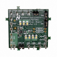
FIGURE 2. One Parallel Connected LED
IN
). With a 1.5x charge pump, the input
LED
(Continued)
) to the power drawn at
20127920
11
Neglecting I
tion, but this impact will be no more than a few percentage
points when several LEDs are driven at full power.
ADJUSTING LED BRIGHTNESS (PWM control)
Perceived LED brightness can be adjusted using a PWM
control signal to turn the LM27961 current sources ON and
OFF at a rate faster than perceptible by the eye. When this
is done, the total brightness perceived is proportional to the
duty cycle (D) of the PWM signal (D = the percentage of time
that the LED is on in every PWM cycle). A simple example: if
the LEDs are driven at 15mA each with a PWM signal that
has a 50% duty cycle, perceived LED brightness will be
about half as bright as compared to when the LEDs are
driven continuously with 15mA. A PWM signal thus provides
brightness (dimming) control for the solution.
The minimum recommended PWM frequency is 100Hz. Fre-
quencies below this may be visibly noticeable as flicker or
blinking. The maximum recommended PWM frequency is
1kHz. Frequencies above this may cause interference with
internal current driver circuitry.
In cases where a PWM signal must be connected to the ENx
pins, measures can be taken to reduce the magnitude of the
charge-pump turn-on voltage spikes. More input capaci-
tance, series resistors and/or ferrite beads may provide ben-
efits.
If the current and voltage spikes can be tolerated, connect-
ing the PWM signal to the EN pin does provide a benefit:
lower supply current when the PWM signal is active. When
the PWM signal is low, the LM27961 will be shutdown and
input current will only be a few micro-amps. This results in a
lower time-averaged input current.
CAPACITOR SELECTION
The LM27961 requires 4 external capacitors for proper op-
eration. Surface-mount multi-layer ceramic capacitors are
recommended. These capacitors are small, inexpensive and
have very low equivalent series resistance (ESR
typ.). Tantalum capacitors, OS-CON capacitors, and alumi-
num electrolytic capacitors are not recommended for use
with the LM27961 due to their high ESR, as compared to
ceramic capacitors.
For most applications, ceramic capacitors with X7R or X5R
temperature characteristic are preferred for use with the
LM27961. These capacitors have tight capacitance toler-
ance (as good as
ture (X7R:
-55˚C to 85˚C).
Capacitors with Y5V or Z5U temperature characteristic are
generally not recommended for use with the LM27961. Ca-
pacitors with these temperature characteristics typically
have wide capacitance tolerance (+80%, -20%) and vary
significantly over temperature (Y5V: +22%, -82% over -30˚C
to +85˚C range; Z5U: +22%, -56% over +10˚C to +85˚C
range). Under some conditions, a nominal 1µF Y5V or Z5U
capacitor could have a capacitance of only 0.1µF. Such
detrimental deviation is likely to cause Y5V and Z5U capaci-
tors to fail to meet the minimum capacitance requirements of
the LM27961.
Q
±
15% over -55˚C to 125˚C; X5R:
will result in a slightly higher efficiency predic-
±
10%) and hold their value over tempera-
±
www.national.com
15% over
<
20mW
Related parts for LM27961TLEV
Image
Part Number
Description
Manufacturer
Datasheet
Request
R

Part Number:
Description:
Accurate, 120 C-150 C Factory Preset Thermostat Lm27 Form
Manufacturer:
National Semiconductor Corporation
Datasheet:

Part Number:
Description:
Factory Preset Thermostat
Manufacturer:
National Semiconductor
Datasheet:
Part Number:
Description:
National Semiconductor [8-Bit D/A Converter]
Manufacturer:
National Semiconductor
Datasheet:
Part Number:
Description:
National Semiconductor [Media Coprocessor]
Manufacturer:
National Semiconductor
Datasheet:
Part Number:
Description:
Digitally Controlled Tone and Volume Circuit with Stereo Audio Power Amplifier, Microphone Preamp Stage and National 3D Sound
Manufacturer:
National Semiconductor
Datasheet:
Part Number:
Description:
Digitally Controlled Tone and Volume Circuit with Stereo Audio Power Amplifier, Microphone Preamp Stage and National 3D Sound
Manufacturer:
National Semiconductor
Datasheet:
Part Number:
Description:
AC97 Rev 2 Codec with Sample Rate Conversion and National 3D Sound
Manufacturer:
National Semiconductor
Part Number:
Description:
Manufacturer:
National Semiconductor
Datasheet:
Part Number:
Description:
Manufacturer:
National Semiconductor
Datasheet:
Part Number:
Description:
General Purpose, Low Voltage, Low Power, Rail-to-Rail Output Operational Amplifiers
Manufacturer:
National Semiconductor
Datasheet:
Part Number:
Description:
8-bit 20 MSPS flash A/D converter.
Manufacturer:
National Semiconductor
Datasheet:
Part Number:
Description:
Low Noise Quad Operational Amplifier
Manufacturer:
National Semiconductor
Datasheet:
Part Number:
Description:
Quad Differential Line Receivers
Manufacturer:
National Semiconductor
Datasheet:
Part Number:
Description:
Quad High Speed Trapezoidal? Bus Transceiver
Manufacturer:
National Semiconductor
Datasheet: