AD8231-EVALZ Analog Devices Inc, AD8231-EVALZ Datasheet - Page 21
AD8231-EVALZ
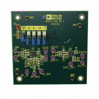
Manufacturer Part Number
AD8231-EVALZ
Description
BOARD EVAL FOR AD8231
Manufacturer
Analog Devices Inc
Specifications of AD8231-EVALZ
Channels Per Ic
2 - Dual
Amplifier Type
Instrumentation
Output Type
Single-Ended
Slew Rate
1.1 V/µs
Current - Output / Channel
70mA
Operating Temperature
-40°C ~ 125°C
Current - Supply (main Ic)
4mA
Voltage - Supply, Single/dual (±)
3 V ~ 6 V, ±1.5 V ~ 3 V
Board Type
Fully Populated
Utilized Ic / Part
AD8231
Silicon Manufacturer
Analog Devices
Application Sub Type
Instrumentation Amplifier
Kit Application Type
Amplifier
Silicon Core Number
AD8231
Kit Contents
Board
Lead Free Status / RoHS Status
Lead free / RoHS Compliant
-3db Bandwidth
-
Lead Free Status / RoHS Status
Lead free / RoHS Compliant, Lead free / RoHS Compliant
Available stocks
Company
Part Number
Manufacturer
Quantity
Price
Company:

Part Number:
AD8231-EVALZ
Manufacturer:
Analog Devices Inc
Quantity:
135


APPLICATIONS INFORMATION
DIFFERENTIAL OUTPUT
Figure 53 shows how to create a differential output in-amp
using the AD8231 uncommitted op amp. Because this
configuration makes use of the reference terminal of the
in-amp, errors from the op amp and resistor mismatch result in
common-mode errors, rather than differential errors. Because
common-mode errors are typically rejected by the next device
in the signal chain, this circuit configuration adds almost no
extra error.
MULTIPLEXING
Figure 53. Differential Output Using Operational Amplifier
Figure 54. Four AD8231s in Multiplexing Configuration
+IN
–IN
3
2
IN-AMP
REF
9
SDN0
SDN1
SDN2
SDN3
4.99kΩ
4.99kΩ
10
–
OP AMP
7
8
V
REF
+
6
+OUT
–OUT
Rev. A | Page 21 of 24
The outputs of both the AD8231 in-amp and op amp are high
impedance in the shutdown state. This feature allows several
AD8231s to be multiplexed together without any external
switches.
All the outputs are connected together and only one amplifier is
turned on at a time. This feature is analogous to the high-Z
mode of the digital tristate logic.
The resistors in the AD8231 instrumentation amplifier create a
resistive path from the output to the reference pin of about
100 kΩ. If a higher output impedance in shutdown mode is
desired, the reference pin can be driven with the op amp of
the AD8231. In this configuration, the output impedance in
shutdown is several GΩ, and many thousand AD8231s can
theoretically be multiplexed in such a way.
The AD8231 can enter and leave shutdown mode very quickly.
However, when the amplifier wakes up and reconnects its input
circuitry, the voltage at its internal input nodes changes dramati-
cally. It takes time for the output of the amplifier to settle. Refer
to Figure 28 through Figure 32 to determine the settling time
for different gains. This settling time limits how quickly the
AD8231 can be multiplexed with the
USING THE AD8231 WITH BIPOLAR SUPPLIES
The AD8231 can be used with bipolar supplies as long as the
maximum voltage drop between the supply rails is kept below
6 V and all input voltages are kept within the supply rails.
With bipolar supplies, the acceptable levels for the digital inputs
A0, A1, A2, CS , and SDN shift. Table 9 shows acceptable values
for low and high signals for both single and dual supplies.
Table 9. Digital Pin Thresholds
Supply Voltage (V)
0 to 5
0 to 3
−2.5 to +2.5
−1.5 to +1.5
Figure 54 shows an example of such a configuration.
Min (V)
0
0
−2.5
−1.5
Low
Max (V)
+1
+0.8
−1.5
−0.7
SDN pin.
Min (V)
4
2.2
1.5
0.7
AD8231
High
Max (V)
5
3
2.5
1.5
Related parts for AD8231-EVALZ
Image
Part Number
Description
Manufacturer
Datasheet
Request
R

Part Number:
Description:
Dual, 16 MHz, Rail-to-Rail FET Input Amplifier
Manufacturer:
Analog Devices
Datasheet:

Part Number:
Description:
±1.7g Dual-Axis IMEMS Accelerometer Evaluation Board
Manufacturer:
Analog Devices Inc
Datasheet:

Part Number:
Description:
Inertial Sensor Evaluation System
Manufacturer:
Analog Devices Inc
Datasheet:
Part Number:
Description:
Manufacturer:
Analog Devices Inc
Datasheet:
Part Number:
Description:
Manufacturer:
Analog Devices Inc
Datasheet:
Part Number:
Description:
Manufacturer:
Analog Devices Inc
Datasheet:
Part Number:
Description:
Manufacturer:
Analog Devices Inc
Datasheet:
Part Number:
Description:
Manufacturer:
Analog Devices Inc
Datasheet:
Part Number:
Description:
Manufacturer:
Analog Devices Inc
Datasheet:
Part Number:
Description:
Manufacturer:
Analog Devices Inc
Datasheet:
Part Number:
Description:
Manufacturer:
Analog Devices Inc
Datasheet:
Part Number:
Description:
Manufacturer:
Analog Devices Inc
Datasheet:
Part Number:
Description:
Manufacturer:
Analog Devices Inc
Datasheet: