AD8231-EVALZ Analog Devices Inc, AD8231-EVALZ Datasheet - Page 22
AD8231-EVALZ
Manufacturer Part Number
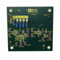
AD8231-EVALZ
Description
BOARD EVAL FOR AD8231
Manufacturer
Analog Devices Inc
Specifications of AD8231-EVALZ
Channels Per Ic
2 - Dual
Amplifier Type
Instrumentation
Output Type
Single-Ended
Slew Rate
1.1 V/µs
Current - Output / Channel
70mA
Operating Temperature
-40°C ~ 125°C
Current - Supply (main Ic)
4mA
Voltage - Supply, Single/dual (±)
3 V ~ 6 V, ±1.5 V ~ 3 V
Board Type
Fully Populated
Utilized Ic / Part
AD8231
Silicon Manufacturer
Analog Devices
Application Sub Type
Instrumentation Amplifier
Kit Application Type
Amplifier
Silicon Core Number
AD8231
Kit Contents
Board
Lead Free Status / RoHS Status
Lead free / RoHS Compliant
-3db Bandwidth
-
Lead Free Status / RoHS Status
Lead free / RoHS Compliant, Lead free / RoHS Compliant
Available stocks
Company
Part Number
Manufacturer
Quantity
Price
Company:

Part Number:
AD8231-EVALZ
Manufacturer:
Analog Devices Inc
Quantity:
135


AD8231
When operating the AD8231 on dual supplies, a level-shift is
typically needed from standard single-supply control logic. One
easy way to accomplish the level-shift is through a single-pole,
double-throw switch, such as the
application schematic for ±2.5 V operation.
SALLEN KEY FILTER
The extra op amp in the AD8231 can be used to create a 2-pole
Sallen Key filter. Such a filter can remove excess noise or
perform antialiasing before an analog-to-digital converter.
Figure 56 shows how to create a 2-pole low-pass Butterworth
filter. Components R1, R2, C1, and C2 set the frequency of the
filter. The ratio of R3 and R4 sets the peaking of the filter. If R4
equals 10 kΩ, R3 should equal 5.9 kΩ for an optimum 2-pole
response.
Depending on the circuitry before and after the AD8231,
a 3-pole filter can be possible. If the previous stage has a small
output impedance, an additional pole can be added before the
in amp (R6, R7, and C4). If the following stage has a high input
impedance, an additional pole can be added after the op amp
(R5 and C3). Peaking from the Sallen Key stage should be
higher to compensate for the extra attenuation of the third pole;
both R3 and R4 should be 10 kΩ for optimum response.
V
ANY VOLTAGE BETWEEN 2.5V AND 9.5V.
MICROCONTROLLER,
DIGITAL
Figure 55. Converting Single-Supply Control Signals to Dual Supply.
CONTROL
DIGITAL
V
(FPGA,
IS THE DIGITAL SUPPLY VOLTAGE. IT CAN BE
DIGITAL
ETC.)
GND
V
DD
+2.5V
–2.5V
+2.5V
–2.5V
+2.5V
–2.5V
A0
A1
A2
EN
–2.5V
ADG633
V
V
SS
DIGITAL
V
DD
GND
ADG633. Figure 55 shows an
AD8231
A0 A1 A2
SDN
+V
–V
CS
S
S
+2.5V
–2.5V
Rev. A | Page 22 of 24
Note that in addition to setting the peaking of the filter, the
ratio R3/R4 also sets the dc gain: G = 1 + R3/R4. If lower dc
gain is required, replace R1 with a voltage divider, where the
output resistance of the divider is equal to the required value of R1.
Figure 56 shows a bias point connected to R4 and the in-amp
reference. The filter stage amplifies the signal around this bias
point. The bias point is typically midsupply and should be low
impedance.
Table 10. Recommended Component Values for Butterworth
Low-Pass Filter in Figure 56
3 dB
Freq
32 Hz
100 Hz
320 Hz
1 kHz
3.2 kHz
10 kHz
32 kHz
Figure 56. Butterworth Low-Pass Filter (Dotted Sections Indicate Optional Poles)
OPTIONAL POLE
R6
R7
C4
Sallen Key
R1, R2
(kΩ)
499
158
49.9
158
49.9
15.8
4.99
IN-AMP
POINT
BIAS
C1, C2
(nF)
10
10
10
1
1
1
1
REF
R1
Before In-Amp
R6, R7
(kΩ)
499
158
49.9
158
49.9
15.8
4.99
R2
C2
SALLEN KEY
(TWO POLE)
OP AMP
Optional Poles
C4
(nF)
4.7
4.7
4.7
0.47
0.47
0.47
0.47
C1
POINT
BIAS
After Op Amp
R5
(kΩ)
49.9
16
4.99
1.6
0.499
0.16
0.049
OPTIONAL POLE
R3
R4
R5
C3
C3
(nF)
100
100
100
100
100
100
100
Related parts for AD8231-EVALZ
Image
Part Number
Description
Manufacturer
Datasheet
Request
R

Part Number:
Description:
Dual, 16 MHz, Rail-to-Rail FET Input Amplifier
Manufacturer:
Analog Devices
Datasheet:

Part Number:
Description:
±1.7g Dual-Axis IMEMS Accelerometer Evaluation Board
Manufacturer:
Analog Devices Inc
Datasheet:

Part Number:
Description:
Inertial Sensor Evaluation System
Manufacturer:
Analog Devices Inc
Datasheet:
Part Number:
Description:
Manufacturer:
Analog Devices Inc
Datasheet:
Part Number:
Description:
Manufacturer:
Analog Devices Inc
Datasheet:
Part Number:
Description:
Manufacturer:
Analog Devices Inc
Datasheet:
Part Number:
Description:
Manufacturer:
Analog Devices Inc
Datasheet:
Part Number:
Description:
Manufacturer:
Analog Devices Inc
Datasheet:
Part Number:
Description:
Manufacturer:
Analog Devices Inc
Datasheet:
Part Number:
Description:
Manufacturer:
Analog Devices Inc
Datasheet:
Part Number:
Description:
Manufacturer:
Analog Devices Inc
Datasheet:
Part Number:
Description:
Manufacturer:
Analog Devices Inc
Datasheet:
Part Number:
Description:
Manufacturer:
Analog Devices Inc
Datasheet: