AD8224-EVALZ Analog Devices Inc, AD8224-EVALZ Datasheet - Page 25
AD8224-EVALZ
Manufacturer Part Number
AD8224-EVALZ
Description
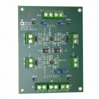
BOARD EVALUATION AD8224
Manufacturer
Analog Devices Inc
Specifications of AD8224-EVALZ
Channels Per Ic
2 - Dual
Amplifier Type
Instrumentation
Output Type
Single-Ended, Rail-to-Rail
Slew Rate
2 V/µs
-3db Bandwidth
1.5MHz
Current - Output / Channel
15mA
Operating Temperature
-40°C ~ 85°C
Current - Supply (main Ic)
750µA
Voltage - Supply, Single/dual (±)
4.5 V ~ 36 V, ±2.25 V ~ 18 V
Board Type
Fully Populated
Utilized Ic / Part
AD8224
Silicon Manufacturer
Analog Devices
Application Sub Type
JFET Input Instrumentation Amplifier
Kit Application Type
Amplifier
Silicon Core Number
AD8224
Kit Contents
Board
Lead Free Status / RoHS Status
Lead free / RoHS Compliant
Available stocks
Company
Part Number
Manufacturer
Quantity
Price
Company:

Part Number:
AD8224-EVALZ
Manufacturer:
Analog Devices Inc
Quantity:
135


DRIVING A DIFFERENTIAL INPUT ADC
The AD8224 can be configured in differential output mode
to drive a differential ADC. Figure 65 illustrates several of the
concepts.
First Antialiasing Filter
The 1 kΩ resistor, 1000 pF capacitor, and 100 pF capacitors in
front of the in-amp form a 76 kHz filter. This is the first of two
antialiasing filters in the circuit and helps to reduce the noise of
the system. The 100 pF capacitors protect against common-
mode RFI signals. Note that they are 5% COG/NPO types.
These capacitors match well over time and temperature,
which keeps the CMRR of the system high over frequency.
Second Antialiasing Filter
An 806 Ω resistor and a 2.7 nF capacitor are located between
each AD8224 output and ADC input. These components
create a 73 kHz low-pass filter for another stage of antialiasing
protection.
These four elements also isolate the ADC from loading the
AD8224. The 806 Ω resistor shields the AD8224 from the
switched capacitor input of the ADC, which looks like a time-
varying load. The 2.7 nF capacitor provides a charge to the
switched capacitor front end of the ADC. If the application
requires a lower frequency antialiasing filter, increase the value
of the capacitor rather than the resistor.
The 806 Ω resistors can also protect an ADC from overvoltages.
Because the AD8224 runs on wider supply voltages than a
typical ADC, there is a possibility of overdriving the ADC. This
is not an issue with a PulSAR® converter, such as the AD7688.
Its input can handle a 130 mA overdrive, which is much higher
than the short-circuit limit of the AD8224.
10µF
10µF
+IN
–IN
+
+
0.1µF
0.1µF
1kΩ
1kΩ
1000pF
100pF
100pF
NPO
NPO
5%
5%
+12V
–12V
(DIFF OUT)
AD8224
+5V REF
+IN2
Figure 65. Driving a Differential ADC
REF2
+OUT
–OUT
Rev. B | Page 25 of 28
806Ω
806Ω
2.7nF
However, other converters have less robust inputs and may need
the added protection.
Reference
The
the AD8224. Because REF2 on the AD8224 is grounded, the
common-mode output voltage is precisely half the reference
voltage, exactly where it needs to be for the ADC.
DRIVING CABLING
All cables have a certain capacitance per unit length, which
varies widely with cable type. The capacitive load from the cable
may cause peaking in the AD8224 output response. To reduce
peaking, use a resistor between the AD8224 and the cable.
Because cable capacitance and desired output response vary
widely, this resistor is best determined empirically. A good
starting point is 50 Ω.
The AD8224 operates at a low enough frequency that
transmission line effects are rarely an issue; therefore, the
resistor need not match the characteristic impedance of
the cable.
0.1µF
ADR435
2.7nF
(SINGLE OUT)
+12V
AD8224
AD8224
(DIFF OUT)
V
ADR435
supplies a reference voltage to both the ADC and
IN+
IN–
IN
GND
V
GND
OUT
VDD
+5V
AD7688
Figure 66. Driving a Cable
10µF
X5R
0.1µF
REF
0.1µF
+5V REF
AD8224
Related parts for AD8224-EVALZ
Image
Part Number
Description
Manufacturer
Datasheet
Request
R

Part Number:
Description:
Single Supply, Rail to Rail Low Power FET-Input Op Amp
Manufacturer:
Analog Devices
Datasheet:

Part Number:
Description:
±1.7g Dual-Axis IMEMS Accelerometer Evaluation Board
Manufacturer:
Analog Devices Inc
Datasheet:

Part Number:
Description:
Inertial Sensor Evaluation System
Manufacturer:
Analog Devices Inc
Datasheet:
Part Number:
Description:
Manufacturer:
Analog Devices Inc
Datasheet:
Part Number:
Description:
Manufacturer:
Analog Devices Inc
Datasheet:
Part Number:
Description:
Manufacturer:
Analog Devices Inc
Datasheet:
Part Number:
Description:
Manufacturer:
Analog Devices Inc
Datasheet:
Part Number:
Description:
Manufacturer:
Analog Devices Inc
Datasheet:
Part Number:
Description:
Manufacturer:
Analog Devices Inc
Datasheet:
Part Number:
Description:
Manufacturer:
Analog Devices Inc
Datasheet:
Part Number:
Description:
Manufacturer:
Analog Devices Inc
Datasheet:
Part Number:
Description:
Manufacturer:
Analog Devices Inc
Datasheet:
Part Number:
Description:
Manufacturer:
Analog Devices Inc
Datasheet: