ADIS16251/PCBZ Analog Devices Inc, ADIS16251/PCBZ Datasheet - Page 17
ADIS16251/PCBZ
Manufacturer Part Number
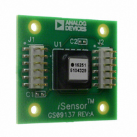
ADIS16251/PCBZ
Description
BOARD EVALUATION FOR ADIS16251
Manufacturer
Analog Devices Inc
Series
iMEMS®, iSensor™r
Specifications of ADIS16251/PCBZ
Sensor Type
Gyroscope, 1 Axis
Sensing Range
±20°/sec, ±40°/sec, ±80°/sec
Interface
SPI Serial
Sensitivity
0.004°/sec/LSB
Voltage - Supply
4.75 V ~ 5.25 V
Embedded
No
Utilized Ic / Part
ADIS16251
Silicon Manufacturer
Analog Devices
Application Sub Type
Angular Rate Sensor / Gyroscope
Kit Application Type
Sensing - Motion / Vibration / Shock
Silicon Core Number
ADIS16251
Kit Contents
Board
Lead Free Status / RoHS Status
Lead free / RoHS Compliant
For Use With
ADISUSBZ - KIT EVAL ADIS W/SOFTWARE USBADISEVALZ - KIT PC EVALUATION W/SOFTWARE
Lead Free Status / RoHS Status
Lead free / RoHS Compliant


STATUS AND DIAGNOSTICS
The ADIS16251 provides a number of status and diagnostic
functions. Table 24 provides a summary of these functions,
along with their appropriate control registers.
Table 24. Status and Diagnostic Functions
Function
Data-Ready I/O Indicator
Self-Test, Mechanical Check For MEMS
Status, Check For Predefined Error
Flash Memory Endurance
Alarms, Configure And Check For User-
Data-Ready I/O Indicator
The data-ready function provides an indication of updated out-
put data. The MSC_CTRL register provides the opportunity to
configure either of the general-purpose I/O pins (DIO1 and DIO2)
as a data-ready indicator signal. After each output register update,
the digital I/O changes states, and then returns to its original state,
creating a pulsed waveform. The duty cycle of that waveform is
between 15% and 35%.
Table 25. MSC_CTRL Register Definition
Address
0x35, 0x34
Table 26. MSC_CTRL Bit Descriptions
Bit
15:11
10
9
8
7:3
2
1
0
Sensor
Conditions
Specific Conditions
Description
Not used
Internal self-test enable
External negative rotation self-test enable
External positive rotation self-test enable
Not used
Data-ready enable
Data-ready polarity
Data-ready line select
1 = enabled
0 = disabled
1 = enabled
0 = disabled
1 = enabled
0 = disabled
1 = enabled
0 = disabled
1 = active high
0 = active low
1 = DIO2
0 = DIO1
Default
0x0000
Format
N/A
Register
MSC_CTRL
MSC_CTRL
STATUS
ENDURANCE
ALM_MAG1/ALM_MAG2
ALM_SMPL1/ALM_SMPL2
ALM_CTRL
Access
R/W
Rev. A | Page 17 of 17
Self-Test
The MSC_CTRL register also provides a self-test function,
which verifies the MEMS sensor’s mechanical integrity. There
are two different self-test options: (1) internal self-test and
(2) external self-test. The internal test provides a simple, two-
step process for checking the MEMS sensor: (1) start the
process by writing a 1 to Bit 10 in the MSC_CTRL register
and (2) check the result by reading Bit 5 of the STATUS
register, after 35 ms.
The external self-test is a static condition that can be
enabled and disabled. In this test, both positive and
negative MEMS sensor movements are available. After
writing to the appropriate control bit, the GYRO_OUT
register reflects the changes after a delay that reflects the
sensor signal chain response time. For example, the standard
49 Hz bandwidth reflects an exponential response with a time
constant of 3.2 ms. If the bandwidth is reduced externally (a
capacitor across RATE and FILT pins) or internally (increasing
the number of filter taps, see SENS/AVG register), this time
constant increases. For the internal self-test option, increasing
the delay can produce false alarms, since the internal timing
for this function is optimized for maximum bandwidth. The
appropriate bit definitions for self-test are listed in
and Table 26.
Status Conditions
The STATUS register contains the following error-condition
flags: Alarm conditions, self-test status, angular rate over range,
SPI communication failure, control register update failure, and
power supply out of range. See Table 27 and Table 28 for the
appropriate register access and bit assignment for each flag.
The bits assigned for checking the power supply range and the
angular rate overrange automatically reset to zero when the
error condition no longer exists. The remaining error-flag
bits in the STATUS register require a read in order to return
them to zero. Note that a STATUS register read clears all of the
bits to zero.
Table 27. STATUS Register Definition
Address
0x3D, 0x3C
Default
0x0000
Format
N/A
ADIS16251
Access
Read-only
Table 25
Related parts for ADIS16251/PCBZ
Image
Part Number
Description
Manufacturer
Datasheet
Request
R

Part Number:
Description:
±1.7g Dual-Axis IMEMS Accelerometer Evaluation Board
Manufacturer:
Analog Devices Inc
Datasheet:

Part Number:
Description:
Inertial Sensor Evaluation System
Manufacturer:
Analog Devices Inc
Datasheet:
Part Number:
Description:
Manufacturer:
Analog Devices Inc
Datasheet:
Part Number:
Description:
Manufacturer:
Analog Devices Inc
Datasheet:
Part Number:
Description:
Manufacturer:
Analog Devices Inc
Datasheet:
Part Number:
Description:
Manufacturer:
Analog Devices Inc
Datasheet:
Part Number:
Description:
Manufacturer:
Analog Devices Inc
Datasheet:
Part Number:
Description:
Manufacturer:
Analog Devices Inc
Datasheet:
Part Number:
Description:
Manufacturer:
Analog Devices Inc
Datasheet:
Part Number:
Description:
Manufacturer:
Analog Devices Inc
Datasheet:
Part Number:
Description:
Manufacturer:
Analog Devices Inc
Datasheet:
Part Number:
Description:
Manufacturer:
Analog Devices Inc
Datasheet:
Part Number:
Description:
Manufacturer:
Analog Devices Inc
Datasheet: