STEVAL-IFS003V1 STMicroelectronics, STEVAL-IFS003V1 Datasheet - Page 10
STEVAL-IFS003V1
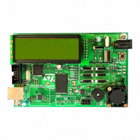
Manufacturer Part Number
STEVAL-IFS003V1
Description
BOARD STLM75/STDS75/ST72F651
Manufacturer
STMicroelectronics
Datasheets
1.STLM75DS2F.pdf
(40 pages)
2.STDS75M2F.pdf
(39 pages)
3.STEVAL-IFS003V1.pdf
(161 pages)
4.STEVAL-IFS003V1.pdf
(4 pages)
Specifications of STEVAL-IFS003V1
Design Resources
STEVAL-IFS003V1 Gerber Files STEVAL-IFS003V1 Schematic STEVAL-IFS003V1 Bill of Materials
Sensor Type
Temperature
Sensing Range
-55°C ~ 125°C
Interface
I²C
Voltage - Supply
7.5 V ~ 19 V
Embedded
Yes, MCU, 8-Bit
Utilized Ic / Part
ST72F651, STDS75, STLM75
Silicon Manufacturer
ST Micro
Silicon Core Number
STLM75/STDS75 And ST72F651AR6
Kit Application Type
Sensing - Temperature
Application Sub Type
Temperature Sensor
Kit Contents
Board
Lead Free Status / RoHS Status
Lead free / RoHS Compliant
Sensitivity
-
Lead Free Status / Rohs Status
Lead free / RoHS Compliant
Other names
497-6238


Operation
2
Note:
10/39
Operation
After each temperature measurement and analog-to-digital conversion, the STDS75 stores
the temperature as a 16-bit two’s complement number in the 2-byte temperature register
(see
temperature is positive or negative:
●
●
The most recently converted digital measurement can be read from the temperature register
at any time. Since temperature conversions are performed in the background, reading the
temperature register does not affect the operation in progress.
Bits 3 through 0 of the temperature register are hardwired to logic '0.' When the STDS75 is
configured for 12-bit resolution, the 12 MSBs (bits 15 through 4) of the temperature register
will contain temperature data. For 11-bit resolution, the 11 MSBs (bits 15 through 5) of the
temperature register will contain data, and bit 4 will read out as logic '0.' For 10-bit
resolution, the 10 MSBs (bits 15 through 6) will contain data, and for 9-bit resolution the
9 MSBs (bits 15 through 7) will contain data and all unused LSBs will contain '0's.
Table 3 on page 15
corresponding temperatures. The data is compared to the values in the T
registers, and then the OS/INT is updated based on the result of the comparison and the
operating mode. The number of T
is equal to the conversion resolution set by the FT1 and FT0 bits in the configuration
register. For example, if the resolution is 9 bits, only the 9 MSBs of T
used by the thermostat comparator. The alarm fault tolerance is controlled by the FTI and
FTO bits in the configuration register. They are used to set up a fault queue. This prevents
false tripping of the OS/INT pin when the STDS75 is used in a noisy environment (see
Table 2 on page
The active state of the OS/INT output can be changed via the polarity (POL) bit in the
configuration register. The power-up default is active-low.
If the user does not wish to use the thermostat capabilities of the STDS75, the OS/INT
output should be left floating.
If the thermostat is not used, the T
system data.
for positive numbers S = 0, and
for negative numbers S = 1.
Table 8: Temperature register
14).
gives examples of 12-bit resolution digital output data and the
Doc ID 13297 Rev 8
OS
OS
format). The most significant bit (S, bit 15) indicates if the
and T
and T
HYS
HYS
bits used during the thermostat comparison
registers can be used for general storage of
OS
and T
OS
and T
HYS
will be
HYS
STDS75
Related parts for STEVAL-IFS003V1
Image
Part Number
Description
Manufacturer
Datasheet
Request
R

Part Number:
Description:
BOARD EVAL SPZB260 MOD FOR STR9
Manufacturer:
STMicroelectronics
Datasheet:

Part Number:
Description:
BOARD EVAL EXTENSION SN250
Manufacturer:
STMicroelectronics
Datasheet:

Part Number:
Description:
BOARD EVAL AB-54003L-512
Manufacturer:
STMicroelectronics
Datasheet:

Part Number:
Description:
BOARD REF DESIGN RF DMOS PWR AMP
Manufacturer:
STMicroelectronics
Datasheet:

Part Number:
Description:
BOARD EVAL PWR AMP AB-84008L-470
Manufacturer:
STMicroelectronics
Datasheet:

Part Number:
Description:
BOARD EVAL FOR STM32F103XX
Manufacturer:
STMicroelectronics
Datasheet:

Part Number:
Description:
BOARD EVAL AB-54003L-512
Manufacturer:
STMicroelectronics
Datasheet:

Part Number:
Description:
BOARD SMART PLUG STM32 SPZB260PR
Manufacturer:
STMicroelectronics
Datasheet:

Part Number:
Description:
BOARD DEMO BLUETOOTH SPBT2532C2
Manufacturer:
STMicroelectronics
Datasheet:
Part Number:
Description:
ZIGBEE USB DONGLE EVAL KIT
Manufacturer:
STMicroelectronics
Datasheet:
Part Number:
Description:
STMicroelectronics [RIPPLE-CARRY BINARY COUNTER/DIVIDERS]
Manufacturer:
STMicroelectronics
Datasheet:
Part Number:
Description:
STMicroelectronics [LIQUID-CRYSTAL DISPLAY DRIVERS]
Manufacturer:
STMicroelectronics
Datasheet:

Part Number:
Description:
BOARD EVAL FOR MEMS SENSORS
Manufacturer:
STMicroelectronics
Datasheet: