RD3172MMA7455L Freescale Semiconductor, RD3172MMA7455L Datasheet - Page 3
RD3172MMA7455L
Manufacturer Part Number
RD3172MMA7455L
Description
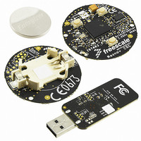
EVAL BOARD FOR MMA7455L
Manufacturer
Freescale Semiconductor
Series
ZSTAR3r
Datasheets
1.RD3172MMA7455L.pdf
(35 pages)
2.RD3172MMA7455L.pdf
(2 pages)
3.RD3172MMA7455L.pdf
(100 pages)
Specifications of RD3172MMA7455L
Design Resources
ZSTAR3 Schematic
Sensor Type
Accelerometer, 3 Axis
Sensing Range
±2g, 4g, 8g
Interface
RF
Sensitivity
16, 32, 64 LSB/g
Voltage - Supply
3V
Embedded
Yes, MCU, 16-Bit
Utilized Ic / Part
MMA7455
Acceleration
5000 g
Sensing Axis
Triple Axis
Output Type
Digital
Interface Type
I2C, SPI
Operating Voltage
3.6 L
Operating Current
490 uA
Maximum Operating Temperature
+ 85 C
Minimum Operating Temperature
- 40 C
Lead Free Status / RoHS Status
Lead free / RoHS Compliant
For Use With/related Products
MMA7455L
Available stocks
Company
Part Number
Manufacturer
Quantity
Price
Company:

Part Number:
RD3172MMA7455L
Manufacturer:
Freescale Semiconductor
Quantity:
135


List of Figures
Pin Connections . . . . . . . . . . . . . . . . . . . . . . . . . . . . . . . . . . . . . . . . . . . . . . . . . . . . . . . . . . . . . . . . . . . . . . . . . . . . . . . . . . . . . . 1
Simplified Accelerometer Functional Block Diagram . . . . . . . . . . . . . . . . . . . . . . . . . . . . . . . . . . . . . . . . . . . . . . . . . . . . . . . . . . 5
Simplified Transducer Physical Model . . . . . . . . . . . . . . . . . . . . . . . . . . . . . . . . . . . . . . . . . . . . . . . . . . . . . . . . . . . . . . . . . . . . . 8
Single Pulse Detection . . . . . . . . . . . . . . . . . . . . . . . . . . . . . . . . . . . . . . . . . . . . . . . . . . . . . . . . . . . . . . . . . . . . . . . . . . . . . . . . 13
Freefall Detection in Pulse Mode . . . . . . . . . . . . . . . . . . . . . . . . . . . . . . . . . . . . . . . . . . . . . . . . . . . . . . . . . . . . . . . . . . . . . . . . 13
Double Pulse Detection . . . . . . . . . . . . . . . . . . . . . . . . . . . . . . . . . . . . . . . . . . . . . . . . . . . . . . . . . . . . . . . . . . . . . . . . . . . . . . . 14
Single Byte Read - The Master is reading one address from the MMA7455L . . . . . . . . . . . . . . . . . . . . . . . . . . . . . . . . . . . . . 17
Multiple Bytes Read - The Master is reading multiple sequential registers from the MMA7455L . . . . . . . . . . . . . . . . . . . . . . . 17
Single Byte Write - The Master (MCU) is writing to a single register of the MMA7455L . . . . . . . . . . . . . . . . . . . . . . . . . . . . . . 17
Multiple Byte Writes - The Master (MCU) is writing to multiple sequential registers of the MMA7455L . . . . . . . . . . . . . . . . . . . 17
SPI Timing Diagram for 8-Bit Register Read (4 Wire Mode) . . . . . . . . . . . . . . . . . . . . . . . . . . . . . . . . . . . . . . . . . . . . . . . . . . . 18
SPI Timing Diagram for 8-Bit Register Read (3 Wire Mode) . . . . . . . . . . . . . . . . . . . . . . . . . . . . . . . . . . . . . . . . . . . . . . . . . . . 18
SPI Timing Diagram for 8-Bit Register Write (3 Wire Mode) . . . . . . . . . . . . . . . . . . . . . . . . . . . . . . . . . . . . . . . . . . . . . . . . . . . 18
Pinout Description . . . . . . . . . . . . . . . . . . . . . . . . . . . . . . . . . . . . . . . . . . . . . . . . . . . . . . . . . . . . . . . . . . . . . . . . . . . . . . . . . . . 19
I
SPI Connection to MCU . . . . . . . . . . . . . . . . . . . . . . . . . . . . . . . . . . . . . . . . . . . . . . . . . . . . . . . . . . . . . . . . . . . . . . . . . . . . . . . 20
Sensing Direction and Output Response at 2g Mode . . . . . . . . . . . . . . . . . . . . . . . . . . . . . . . . . . . . . . . . . . . . . . . . . . . . . . . . 28
Recommended PCB Land Pattern for the 5 x 3 mm LGA Package . . . . . . . . . . . . . . . . . . . . . . . . . . . . . . . . . . . . . . . . . . . . . . 29
Incorrect PCB Top Metal Pattern Under Package . . . . . . . . . . . . . . . . . . . . . . . . . . . . . . . . . . . . . . . . . . . . . . . . . . . . . . . . . . . 30
Correct PCB Top Metal Pattern Under Package . . . . . . . . . . . . . . . . . . . . . . . . . . . . . . . . . . . . . . . . . . . . . . . . . . . . . . . . . . . . 30
Recommended PCB Land Pad, Solder Mask, and Signal Trace Near Package Design . . . . . . . . . . . . . . . . . . . . . . . . . . . . . . 30
Stencil Design Guidelines . . . . . . . . . . . . . . . . . . . . . . . . . . . . . . . . . . . . . . . . . . . . . . . . . . . . . . . . . . . . . . . . . . . . . . . . . . . . . . 31
Temperature Coefficient of Offset (TCO) and Temperature Coefficient of Sensitivity (TCS) Distribution Charts . . . . . . . . . . . 32
MMA7455L Current Distribution Charts . . . . . . . . . . . . . . . . . . . . . . . . . . . . . . . . . . . . . . . . . . . . . . . . . . . . . . . . . . . . . . . . . . . 32
Sensors
Freescale Semiconductor
2
C Connection to MCU . . . . . . . . . . . . . . . . . . . . . . . . . . . . . . . . . . . . . . . . . . . . . . . . . . . . . . . . . . . . . . . . . . . . . . . . . . . . . . . 19
MMA7455L
3
Related parts for RD3172MMA7455L
Image
Part Number
Description
Manufacturer
Datasheet
Request
R

Part Number:
Description:
Manufacturer:
Freescale Semiconductor, Inc
Datasheet:
Part Number:
Description:
Manufacturer:
Freescale Semiconductor, Inc
Datasheet:
Part Number:
Description:
Manufacturer:
Freescale Semiconductor, Inc
Datasheet:
Part Number:
Description:
Manufacturer:
Freescale Semiconductor, Inc
Datasheet:
Part Number:
Description:
Manufacturer:
Freescale Semiconductor, Inc
Datasheet:
Part Number:
Description:
Manufacturer:
Freescale Semiconductor, Inc
Datasheet:
Part Number:
Description:
Manufacturer:
Freescale Semiconductor, Inc
Datasheet:
Part Number:
Description:
Manufacturer:
Freescale Semiconductor, Inc
Datasheet:
Part Number:
Description:
Manufacturer:
Freescale Semiconductor, Inc
Datasheet:
Part Number:
Description:
Manufacturer:
Freescale Semiconductor, Inc
Datasheet:
Part Number:
Description:
Manufacturer:
Freescale Semiconductor, Inc
Datasheet:
Part Number:
Description:
Manufacturer:
Freescale Semiconductor, Inc
Datasheet:
Part Number:
Description:
Manufacturer:
Freescale Semiconductor, Inc
Datasheet:
Part Number:
Description:
Manufacturer:
Freescale Semiconductor, Inc
Datasheet:
Part Number:
Description:
Manufacturer:
Freescale Semiconductor, Inc
Datasheet: