KITMPR03XEVM Freescale Semiconductor, KITMPR03XEVM Datasheet - Page 20
KITMPR03XEVM
Manufacturer Part Number
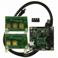
KITMPR03XEVM
Description
KIT EVAL FOR MPR03X
Manufacturer
Freescale Semiconductor
Specifications of KITMPR03XEVM
Sensor Type
Touch, Capacitive
Interface
I²C
Voltage - Supply
1.71 V ~ 2.75 V
Embedded
Yes, Other
Utilized Ic / Part
MPR031
Maximum Operating Temperature
+ 85 C
Minimum Operating Temperature
- 40 C
Description/function
Proximity Sensor
Lead Free Status / RoHS Status
Lead free / RoHS Compliant
Sensitivity
-
Sensing Range
-
Lead Free Status / Rohs Status
Lead free / RoHS Compliant
For Use With/related Products
MPR031, MPR032


MPR03X
20
8
8.1
The MPR03X has three levels of filtering. The first and second level filters will allow the application to condition the signal for
undesired input variation. The third level filter can be configured to reject touch stimulus and be used as a baseline for touch
detection. Each level of filtering will be further described in this section.
8.2
The first level filter is designed to filter high frequency noise by averaging samples taken over short periods of time. The number
of samples can be configured to equal a set of values ranging from 6 to 34 samples. This value is set by the FFI in the AFE
Configuration Register
the Filter Configuration Register
Note that the electrode charge time must be configured for the capacitance in the application. The resulting value will affect the
period of the first level filter.
8.3
The second level filter is designed to filter low frequency noise and reject false touches due to inconsistent data. The number of
samples can be configured to equal a set of values ranging from 4 to 18. This value is set by the SFI in the Filter Configuration
Register
(Section
Note that the ESI (Electrode Sample Interval) must be configured to accommodate the low power requirements of a system.
Thus, the resulting value will affect the period of the second level filter.
The raw data from the second level of filtering is output in the Filtered Data High and Filtered Data Low registers, as shown in
Section
8.3.1
The Filter Configuration register is used to set. The address of the Electrode Configuration Register is 0x43.
5.3.
8.3.1).
Filtering
Introduction
First Level
Second Level
(Section
Filter Configuration Register
Reset:
8.3.1). The timing of this filter is determined by the configuration of ESI in the Filter Configuration Register
W
R
(Section
7
0
7.4.1). The timing of this filter is determined by the configuration of the electrode charge time in
(Section
= Unimplemented
CDT
6
0
8.3.1).
Figure 26. Filter Configuration Register
5
0
4
0
SFI
3
0
2
0
ESI
1
0
Freescale Semiconductor
0
0
Sensors
Related parts for KITMPR03XEVM
Image
Part Number
Description
Manufacturer
Datasheet
Request
R

Part Number:
Description:
Manufacturer:
Freescale Semiconductor, Inc
Datasheet:
Part Number:
Description:
Manufacturer:
Freescale Semiconductor, Inc
Datasheet:
Part Number:
Description:
Manufacturer:
Freescale Semiconductor, Inc
Datasheet:
Part Number:
Description:
Manufacturer:
Freescale Semiconductor, Inc
Datasheet:
Part Number:
Description:
Manufacturer:
Freescale Semiconductor, Inc
Datasheet:
Part Number:
Description:
Manufacturer:
Freescale Semiconductor, Inc
Datasheet:
Part Number:
Description:
Manufacturer:
Freescale Semiconductor, Inc
Datasheet:
Part Number:
Description:
Manufacturer:
Freescale Semiconductor, Inc
Datasheet:
Part Number:
Description:
Manufacturer:
Freescale Semiconductor, Inc
Datasheet:
Part Number:
Description:
Manufacturer:
Freescale Semiconductor, Inc
Datasheet:
Part Number:
Description:
Manufacturer:
Freescale Semiconductor, Inc
Datasheet:
Part Number:
Description:
Manufacturer:
Freescale Semiconductor, Inc
Datasheet:
Part Number:
Description:
Manufacturer:
Freescale Semiconductor, Inc
Datasheet:
Part Number:
Description:
Manufacturer:
Freescale Semiconductor, Inc
Datasheet:
Part Number:
Description:
Manufacturer:
Freescale Semiconductor, Inc
Datasheet: