KITMPR03XEVM Freescale Semiconductor, KITMPR03XEVM Datasheet - Page 21
KITMPR03XEVM
Manufacturer Part Number
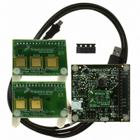
KITMPR03XEVM
Description
KIT EVAL FOR MPR03X
Manufacturer
Freescale Semiconductor
Specifications of KITMPR03XEVM
Sensor Type
Touch, Capacitive
Interface
I²C
Voltage - Supply
1.71 V ~ 2.75 V
Embedded
Yes, Other
Utilized Ic / Part
MPR031
Maximum Operating Temperature
+ 85 C
Minimum Operating Temperature
- 40 C
Description/function
Proximity Sensor
Lead Free Status / RoHS Status
Lead free / RoHS Compliant
Sensitivity
-
Sensing Range
-
Lead Free Status / Rohs Status
Lead free / RoHS Compliant
For Use With/related Products
MPR031, MPR032


Sensors
Freescale Semiconductor
8.4
The Third Level Filter is designed for varying implementations. It can be used as either an additional low pass filter for the
electrode data or a baseline for touch detection. For it to function as a baseline filter, it must be used in conjunction with the touch
detection system described in the next chapter. To use the filter as an additional layer for low pass filtering, the touch detection
system must be disabled by setting all of the touch thresholds to zero (refer to
level of filter will be used as a baseline filter. The primary difference between these implementations is this: if a touch is detected
the baseline filter will hold its current value until the touch is released. The touch/release configuration will be described in
Chapter
When a touch is not currently detected, the baseline filter will operate based on a few conditions. These are configured through
a set of registers including the Max Half Delta Register, the Noise Half Delta Register, and the Noise Count Limit.
8.4.1
The Max Half Delta register is used to set the Max Half Delta for the Third Level Filter. The address of the Max Half Delta Register
is 0x26.
Table 13. Filter Configuration Register Field Descriptions
Table 14. Max Half Delta Register Field Descriptions
9.
Third Level Filter
Max Half Delta Register
Reset:
Field
Field
MHD
CDT
ESI
SFI
7:5
4:3
2:0
5:0
W
R
7
0
0
= Unimplemented
Charge Discharge Time – The Charge Discharge Time field selects the amount
of time an electrode charges and discharges.
000 Encoding 0 – Invalid
001 Encoding 1 – Time is set to 0.5 μs
010 Encoding 2 – Time is set to 1 μs
~
111 Encoding 7 – Time is set to 32 μs.
Second Filter Iterations – The Second Filter Iterations field selects the number of
samples taken for the second level filter.
00 Encoding 0 – Number of samples is set to 4
01 Encoding 1 – Number of samples is set to 6
10 Encoding 2 – Number of samples is set to 10
11 Encoding 3 – Number of samples is set to 18
Electrode Sample Interval – The Electrode Sample Interval field selects the
period between samples used for the second level of filtering.
000 Encoding 0 – Period set to 1 ms
001 Encoding 1 – Period set to 2 ms
~
111 Encoding 7 – Period set to 128 ms
Max Half Delta – The Max Half Delta determines the largest magnitude of
variation to pass through the third level filter.
000000 DO NOT USE THIS CODE
000001 Encoding 1 – Sets the Max Half Delta to 1
~
111111 Encoding 63 – Sets the Max Half Delta to 63
6
0
0
Figure 27. Max Half Delta Register
5
0
4
0
Description
Description
3
0
Section
MHD
2
0
9.2). Although, in most cases the third
1
0
0
0
MPR03X
21
Related parts for KITMPR03XEVM
Image
Part Number
Description
Manufacturer
Datasheet
Request
R

Part Number:
Description:
Manufacturer:
Freescale Semiconductor, Inc
Datasheet:
Part Number:
Description:
Manufacturer:
Freescale Semiconductor, Inc
Datasheet:
Part Number:
Description:
Manufacturer:
Freescale Semiconductor, Inc
Datasheet:
Part Number:
Description:
Manufacturer:
Freescale Semiconductor, Inc
Datasheet:
Part Number:
Description:
Manufacturer:
Freescale Semiconductor, Inc
Datasheet:
Part Number:
Description:
Manufacturer:
Freescale Semiconductor, Inc
Datasheet:
Part Number:
Description:
Manufacturer:
Freescale Semiconductor, Inc
Datasheet:
Part Number:
Description:
Manufacturer:
Freescale Semiconductor, Inc
Datasheet:
Part Number:
Description:
Manufacturer:
Freescale Semiconductor, Inc
Datasheet:
Part Number:
Description:
Manufacturer:
Freescale Semiconductor, Inc
Datasheet:
Part Number:
Description:
Manufacturer:
Freescale Semiconductor, Inc
Datasheet:
Part Number:
Description:
Manufacturer:
Freescale Semiconductor, Inc
Datasheet:
Part Number:
Description:
Manufacturer:
Freescale Semiconductor, Inc
Datasheet:
Part Number:
Description:
Manufacturer:
Freescale Semiconductor, Inc
Datasheet:
Part Number:
Description:
Manufacturer:
Freescale Semiconductor, Inc
Datasheet: