PIC16F690DM-PCTLHS Microchip Technology, PIC16F690DM-PCTLHS Datasheet - Page 10
PIC16F690DM-PCTLHS
Manufacturer Part Number
PIC16F690DM-PCTLHS
Description
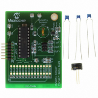
BOARD DEMO PICTAIL HUMIDITY SNSR
Manufacturer
Microchip Technology
Series
PICtail™r
Datasheets
1.PIC16F690DM-PCTLHS.pdf
(36 pages)
2.PIC16F690DM-PCTLHS.pdf
(32 pages)
3.PIC16F690DM-PCTLHS.pdf
(306 pages)
4.PIC16F690DM-PCTLHS.pdf
(14 pages)
Specifications of PIC16F690DM-PCTLHS
Sensor Type
Humidity
Sensing Range
1 ~ 99% RH
Interface
Analog
Voltage - Supply
5V
Embedded
Yes, MCU, 8-Bit
Utilized Ic / Part
MCP6291, PIC16F690
Processor To Be Evaluated
MCP6291 and PIC16F690
Interface Type
ICSP
Lead Free Status / RoHS Status
Lead free / RoHS Compliant
For Use With
AC162061 - HEADER INTRFC MPLAB ICD2 20PIN
Sensitivity
-
Lead Free Status / RoHS Status
Lead free / RoHS Compliant, Lead free / RoHS Compliant


AN1016
Normal Resolution Measurements
The circuit in Figure 3 does not attenuate the square
wave, making it possible to measure larger capacitors.
The C
Figure 9
between the values read from an HP4285A LCR meter
and the circuit in Figure 3. These measurements were
taken across a range of allowed C
FIGURE 9:
Discrepancy.
HS1101LF Sensor Measurements
The circuit in Figure 3 was used to measure the
HS1101LF relative humidity sensor. The measurement
resolution is 0.1 pF / count (0.6% RH change per
count) and R
show how the sensor reacted when it was breathed on
for about half second; the result is the impulse
response of the sensor.
FIGURE 10:
Response.
DS01016A-page 10
200
195
190
185
180
175
170
165
SEN
-10%
10%
-2%
-4%
-6%
-8%
8%
6%
4%
2%
0%
-5
1p
resolution is 0.1 pF / count.
1.E+00
shows
0
INT
5 10 15 20 25 30 35 40 45
is 6.65 M . The curves in Figure 10
C
SEN
10p
1.E+01
the
breathed on sensor
C
HS1101LF Impulse
Not Corrected
Corrected:
C
B
Time (s)
PAR
1
SEN
= 0.09987 pF / count
measurement
= 0.270 pF
C
100p
1.E+02
SEN
Measurement
(F)
SEN
1.E+03
RH
values.
1n
discrepancy
22%
20%
18%
16%
14%
12%
10%
8%
1.E+04
10n
LESSONS LEARNED
Several important lessons were learned in the process
of building, measuring and debugging this design.
Ratiometric Design
This design assumes V
(e.g., two lithium batteries). To avoid supply rejection
errors, and to make the design simpler to implement, a
ratiometric approach was very helpful. The implemen-
tation is as follows:
• The square wave V
• V
• V
• CV
Reference Voltages Chosen
The reference voltages (V
selected carefully. The analog components need to
stay within their allowed ranges, but V
to be as far apart as possible for accuracy reasons:
• The lower CV
• The comparator’s V
• The op amp’s output should stay above 0.2V to
For these reasons, the design uses V
and V
Choosing the Microcontroller
The PIC16F690 has several key features that help this
design:
• Comparator latch makes the firmware simpler and
• The comparator can be connected internally to
• It has an accurate internal oscillator.
• It operates over the required supply range.
so the voltage V
ratiometric (the other internal reference is not)
upper range (±1.04% vs. ±1.56%).
which is at its worst case value (V
V
0.3V to maintain accuracy and avoid overdrive
recovery problems (about 0.1V
V
avoids delay in a firmware loop.
the reference (CV
CM
CM
DD
DD
REF
RH
= 3.0V (it is not ratiometric).
= 3.0V).
is ratiometric
and R
= 0.500V
reference (used for V
INT
REF
make the current I
DD
SEN
range is more accurate than the
REF
in the lower CV
INT
CMR
is ratiometric
) and to the board.
© 2005 Microchip Technology Inc.
DD
is ratiometric
range is V
RH
ranges from 3.0V to 5.5V
RH
and V
DD
and V
INT
DD
when
REF
DD
RH
RL
ratiometric,
/2) when
RL
RL
– 1.5V,
) need to be
and V
range.
) is
= 0.125V
RL
need
DD
Related parts for PIC16F690DM-PCTLHS
Image
Part Number
Description
Manufacturer
Datasheet
Request
R

Part Number:
Description:
Manufacturer:
Microchip Technology Inc.
Datasheet:
Part Number:
Description:
Manufacturer:
Microchip Technology Inc.
Datasheet:
Part Number:
Description:
Manufacturer:
Microchip Technology Inc.
Datasheet:
Part Number:
Description:
Manufacturer:
Microchip Technology Inc.
Datasheet:
Part Number:
Description:
Manufacturer:
Microchip Technology Inc.
Datasheet:
Part Number:
Description:
Manufacturer:
Microchip Technology Inc.
Datasheet:
Part Number:
Description:
Manufacturer:
Microchip Technology Inc.
Datasheet:
Part Number:
Description:
Manufacturer:
Microchip Technology Inc.
Datasheet: