PIC16F690DM-PCTLHS Microchip Technology, PIC16F690DM-PCTLHS Datasheet - Page 5
PIC16F690DM-PCTLHS
Manufacturer Part Number
PIC16F690DM-PCTLHS
Description
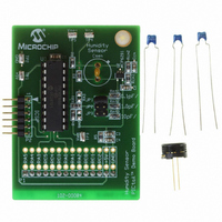
BOARD DEMO PICTAIL HUMIDITY SNSR
Manufacturer
Microchip Technology
Series
PICtail™r
Datasheets
1.PIC16F690DM-PCTLHS.pdf
(36 pages)
2.PIC16F690DM-PCTLHS.pdf
(32 pages)
3.PIC16F690DM-PCTLHS.pdf
(306 pages)
4.PIC16F690DM-PCTLHS.pdf
(14 pages)
Specifications of PIC16F690DM-PCTLHS
Sensor Type
Humidity
Sensing Range
1 ~ 99% RH
Interface
Analog
Voltage - Supply
5V
Embedded
Yes, MCU, 8-Bit
Utilized Ic / Part
MCP6291, PIC16F690
Processor To Be Evaluated
MCP6291 and PIC16F690
Interface Type
ICSP
Lead Free Status / RoHS Status
Lead free / RoHS Compliant
For Use With
AC162061 - HEADER INTRFC MPLAB ICD2 20PIN
Sensitivity
-
Lead Free Status / RoHS Status
Lead free / RoHS Compliant, Lead free / RoHS Compliant


Top Level Algorithm
Figure 5 shows the flow chart for the top level program.
This implementation includes averaging eight C
readings together.
FIGURE 5:
The algorithm shown does not include any accuracy
improvements. The user can add code to either correct
the reference levels (V
ADC, or calibrate the entire circuit’s errors (including
temperature drift).
© 2005 Microchip Technology Inc.
“capacitance.asm”
Divide Accumulated
“humidity.asm”
Accumulate
C
count = 8
Initialize
SEN
C
Main
Call
Call
SEN
Is
?
by 8
Yes
Top Level Flow Chart.
RL
and V
No
RH
), using the internal
SEN
Capacitance Module
Table 2 shows the algorithm for the capacitance
module, and includes the PICmicro microcontroller’s
pin states.
The pin assignments on the Humidity Sensor PICtail™
Demo Board [15] used for the measurements in this
application note are:
• P1 = RC2 (V
• P2 = RC1 (V
• P3 = RA4/T1G
• P4 = RC4/C2OUT
Pin P2 is configured as the comparator’s input during
the measurements. This gives the comparator time to
settle before the measurements are made.
TABLE 2:
Relative Humidity Module
Once C
relative humidity (RH) for the HS1101LF sensor can be
estimated. The conversion is accomplished using a
piecewise linear interpolation table [11]. Appendix A:
“Piecewise Linear Interpolation Table” contains
details on the design of this table.
Initialize V
Set V
Detect when V
Delay
Positive V
Start count k
Set V
Stop count k
Delay
Negative V
Start count k
Set V
Stop count k
Delay
Note 1:
(Move V
(Move V
(Move V
REF
REF
REF
2:
SEN
Algorithm Steps
to V
to V
to V
SEN
SEN
SEN
SEN
V
These are lower range levels in the
PIC16F690’s V
The counts k
each PICmicro instruction cycle
(T
SEN
SEN
has been calculated and averaged, the
1
2
RL
1
2
CLK
RL
RH
RL
when V
when V
when V
when V
INT
SEN
SEN
to < V
from < V
from > V
Slope (Note 2)
(Note 1)
= 0.125V
CAPACITANCE ALGORITHM
Slope
)
= 0.5 μs)
)
< V
RL
SEN
SEN
SEN
SEN
RL
)
RL
RH
1
DD
and k
= V
= V
REF
= V
= V
to > V
to < V
and V
RL
RH
RH
RL
(CV
2
RH
increment once for
RL
AN1016
RH
REF
)
)
= 0.500V
DS01016A-page 5
).
Pin States
P1
1
0
1
DD
input
input
input
P2
.
Related parts for PIC16F690DM-PCTLHS
Image
Part Number
Description
Manufacturer
Datasheet
Request
R

Part Number:
Description:
Manufacturer:
Microchip Technology Inc.
Datasheet:
Part Number:
Description:
Manufacturer:
Microchip Technology Inc.
Datasheet:
Part Number:
Description:
Manufacturer:
Microchip Technology Inc.
Datasheet:
Part Number:
Description:
Manufacturer:
Microchip Technology Inc.
Datasheet:
Part Number:
Description:
Manufacturer:
Microchip Technology Inc.
Datasheet:
Part Number:
Description:
Manufacturer:
Microchip Technology Inc.
Datasheet:
Part Number:
Description:
Manufacturer:
Microchip Technology Inc.
Datasheet:
Part Number:
Description:
Manufacturer:
Microchip Technology Inc.
Datasheet: