PIC16F690DM-PCTLHS Microchip Technology, PIC16F690DM-PCTLHS Datasheet - Page 2
PIC16F690DM-PCTLHS
Manufacturer Part Number
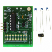
PIC16F690DM-PCTLHS
Description
BOARD DEMO PICTAIL HUMIDITY SNSR
Manufacturer
Microchip Technology
Series
PICtail™r
Datasheets
1.PIC16F690DM-PCTLHS.pdf
(36 pages)
2.PIC16F690DM-PCTLHS.pdf
(32 pages)
3.PIC16F690DM-PCTLHS.pdf
(306 pages)
4.PIC16F690DM-PCTLHS.pdf
(14 pages)
Specifications of PIC16F690DM-PCTLHS
Sensor Type
Humidity
Sensing Range
1 ~ 99% RH
Interface
Analog
Voltage - Supply
5V
Embedded
Yes, MCU, 8-Bit
Utilized Ic / Part
MCP6291, PIC16F690
Processor To Be Evaluated
MCP6291 and PIC16F690
Interface Type
ICSP
Lead Free Status / RoHS Status
Lead free / RoHS Compliant
For Use With
AC162061 - HEADER INTRFC MPLAB ICD2 20PIN
Sensitivity
-
Lead Free Status / RoHS Status
Lead free / RoHS Compliant, Lead free / RoHS Compliant


AN1016
FIGURE 1:
Figure 2 shows the timing of the main waveforms. The
supply voltages are V
I
of –I
FIGURE 2:
Circuit
Figure 3 shows the circuit. The PICmicro
troller (U
voltage, V
external to U
DS01016A-page 2
INT
Threshold Crossing
Voltage-to-Current
has a positive value of I
INTM
V
V
Timing Counter
V
Square Wave
SEN
I
REF
Calculations
INT
INT
V
V
Conversion
I
Integrator
INT
INT
SEN
Detector
1
Source
(I
) outputs a logic level at pin P1, making the
INTP
INT,
1
(square wave)
(square wave)
(triangle wave)
form an inverting (Miller) integrator. V
and I
either 0V or V
–I
I
V
V
V
INTP
0V
0V
0V
INTM
INTM
t
DD
DD
DD
1
DD
Integrator Block Diagram.
Timing Diagram.
are nearly equal magnitudes).
and ground (0V). The current
V
RH
INTP
, and a negative value
DD
Magnitude Control
. The components
V
V
t
RL
2
RH
®
microcon-
V
RL
SEN
is a triangle wave whose slope depends on C
firmware, comparator and reference (V
control the circuit as described before.
The power supply voltages (V
assumed to vary between 3.0V and 5.5V. This design
uses 1% resistors for low cost. The SR latch and
Timer1 in U
triangle wave.
FIGURE 3:
The voltage V
(negative) slope when V
EQUATION 1:
The voltage reference, V
a lower reference voltage, V
upper reference voltage, V
selected to be within the op amp’s output voltage
Note 1: C
P4
P3
100 nF
PIC16F690
----------------
C
Timer1
V
Comparator
2: R
Latch
1
I
I
U
SEN
SR
INT
t
INT
1
1
V
sitic capacitance. C
at the op amp’s inverting input pin to
improve the op amp’s stability and
eliminate any dynamic current through
C
calculate C
REF
time the rise and fall times of the V
V
CG
CG
INT
=
=
=
DD_DIG
SEN
.
is the sensor’s case-to-ground para-
V
---------------------------- -
------------ - ,
C
V
---------------------------- - ,
is chosen to minimize the effort to
I
R
INT
INT
SEN
INT
INT
P1
P2
R
will have a constant positive
INT
–
–
Op Amp Integrator Circuit.
C
V
V
SEN
© 2005 Microchip Technology Inc.
V
V
INT
SEN
REF,
MCP6291
INT
SEN
CM
CM
I
INT
.
is 0V (V
RH
is set to one of two levels:
100 nF
6.65 M
RL
is constant
DD_DIG
C
C
R
V
(0.500V
CG
C
SEN
2
100 nF
INT
INT
(0.125V
CG
U
C
DD
should be placed
2
is constant
CM
):
and V
DD
DD
REF
). V
V
I
), and an
CM
INT
DD
SEN
) in U
RL
V
R
20 k
R
20 k
) were
DD
CM1
CM2
. The
was
SEN
1
Related parts for PIC16F690DM-PCTLHS
Image
Part Number
Description
Manufacturer
Datasheet
Request
R

Part Number:
Description:
Manufacturer:
Microchip Technology Inc.
Datasheet:
Part Number:
Description:
Manufacturer:
Microchip Technology Inc.
Datasheet:
Part Number:
Description:
Manufacturer:
Microchip Technology Inc.
Datasheet:
Part Number:
Description:
Manufacturer:
Microchip Technology Inc.
Datasheet:
Part Number:
Description:
Manufacturer:
Microchip Technology Inc.
Datasheet:
Part Number:
Description:
Manufacturer:
Microchip Technology Inc.
Datasheet:
Part Number:
Description:
Manufacturer:
Microchip Technology Inc.
Datasheet:
Part Number:
Description:
Manufacturer:
Microchip Technology Inc.
Datasheet: