DM164120-1 Microchip Technology, DM164120-1 Datasheet - Page 23
DM164120-1
Manufacturer Part Number
DM164120-1
Description
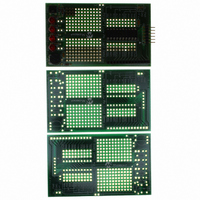
BOARD DEMO PICKIT 2 LP COUNT
Manufacturer
Microchip Technology
Type
MCUr
Datasheet
1.DM164120-1.pdf
(42 pages)
Specifications of DM164120-1
Contents
3 Boards (1 Populated, 2 Bare)
Processor To Be Evaluated
PIC16F690
Silicon Manufacturer
Microchip
Core Architecture
PIC
Core Sub-architecture
PIC16
Silicon Core Number
PIC16F
Silicon Family Name
PIC16F6xxx
Rohs Compliant
Yes
Lead Free Status / RoHS Status
Lead free / RoHS Compliant
For Use With/related Products
28-pin PIC16C, 16F, 18C, 18F
Lead Free Status / Rohs Status
Lead free / RoHS Compliant
Available stocks
Company
Part Number
Manufacturer
Quantity
Price
Company:

Part Number:
DM164120-1
Manufacturer:
Microchip Technology
Quantity:
135


© 2005 Microchip Technology Inc.
3.2.4
This lesson shows how to configure the ADC, run a conversion, read the analog voltage
controlled by the potentiometer (RP1) on the board, and display the high order 4 bits
on the display.
The PIC16F690 has an on board Analog-to-Digital Converter (ADC) with 10 bits of
resolution on any of 11 channels. The converter can be referenced to the device’s V
or an external voltage reference. The LPC Demo Board references it to V
provided by the USB cable. The answer from the ADC is represented by a ratio of the
voltage to the reference.
Converting the answer from the ADC back to voltage requires solving for V.
Two of the three factors on the right side of the equation are constants and may be
calculated in advance. This eliminates the need to actually divide, but still requires fixed
or floating point multiply to solve the equation on the fly.
However, sometimes, such as when reading a sensor, calculating the voltage is only
the first step. There may be additional math to calculate the meaningful data from the
sensor. For example, when reading a thermistor, calculating the voltage is only the first
step on the way to getting the temperature.
There are other means to convert ADC values, including a straight table look-up or a
piece-wise linear interpolation. Each of these represents different speed/memory
trade-offs.
The schematic (Appendix A. “Hardware Schematics”) shows the wiper on the
potentiometer is connected to pin RA0 on the PIC16F690.
Here’s the checklist for this lesson:
• Configure PORTA as an analog input, TRISA<0> = 1, ANSEL<0> = 1
• Select clock scaling in ADCON1.
• Select channel, justification and V
ADC = V/V
V = ADC/1023 * V
Lesson 4: Analog-to-Digital
REF
* 1023
REF
LPC Demo Board Lessons
REF
source in ADCON0.
DS51556A-page 19
DD
as
DD
Related parts for DM164120-1
Image
Part Number
Description
Manufacturer
Datasheet
Request
R

Part Number:
Description:
SERIES CONNECTION; 16 DIODES
Manufacturer:
Altech Corp.
Datasheet:

Part Number:
Description:
Manufacturer:
Microchip Technology Inc.
Datasheet:
Part Number:
Description:
Manufacturer:
Microchip Technology Inc.
Datasheet:
Part Number:
Description:
Manufacturer:
Microchip Technology Inc.
Datasheet:
Part Number:
Description:
Manufacturer:
Microchip Technology Inc.
Datasheet:
Part Number:
Description:
Manufacturer:
Microchip Technology Inc.
Datasheet:
Part Number:
Description:
Manufacturer:
Microchip Technology Inc.
Datasheet:
Part Number:
Description:
Manufacturer:
Microchip Technology Inc.
Datasheet:
Part Number:
Description:
Manufacturer:
Microchip Technology Inc.
Datasheet: