ATSTK500 Atmel, ATSTK500 Datasheet - Page 13
ATSTK500
Manufacturer Part Number
ATSTK500
Description
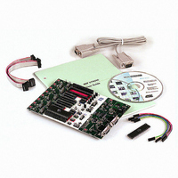
PROGRAMMER AVR STARTER KIT
Manufacturer
Atmel
Series
AVR®r
Type
MCUr
Specifications of ATSTK500
Contents
Board, Cable, CD and Documentation
Data Bus Width
8 bit
Interface Type
RS-232
For Use With/related Products
Atmel AVR Devices
For Use With
ATADAPCAN01 - EXTENSION CAN ADD-ON TO STK500/1
Lead Free Status / RoHS Status
Lead free / RoHS Compliant


3.3
3.4
AVR STK500 User Guide
Connection of
LEDs and
Switches
Port Connectors
Figure 3-4. Connection of LEDs and Switches to I/O Port Headers
Any I/O port of the AVR can be connected to the LEDs and switches using the 10-wire
cables. The headers are supplied with VTG (target V
signal lines.
The pinout for the I/O port headers is explained in Figure 3-5. The square marking indi-
cates pin 1.
Figure 3-5. General Pinout of I/O Port Headers
The PORTE/AUX header has some special signals and functions in addition to the
PORTE pins. The pinout of this header is shown in Figure 3-6.
GND
Px0
Px2
Px4
Px6
PORTx
1 2
Px1
Px3
Px5
Px7
VTG
CC
) and GND lines in addition to the
Hardware Description
1925C–AVR–3/03
3-3
Related parts for ATSTK500
Image
Part Number
Description
Manufacturer
Datasheet
Request
R

Part Number:
Description:
DEV KIT FOR AVR/AVR32
Manufacturer:
Atmel
Datasheet:

Part Number:
Description:
INTERVAL AND WIPE/WASH WIPER CONTROL IC WITH DELAY
Manufacturer:
ATMEL Corporation
Datasheet:
Part Number:
Description:
Low-Voltage Voice-Switched IC for Hands-Free Operation
Manufacturer:
ATMEL Corporation
Datasheet:
Part Number:
Description:
MONOLITHIC INTEGRATED FEATUREPHONE CIRCUIT
Manufacturer:
ATMEL Corporation
Datasheet:
Part Number:
Description:
AM-FM Receiver IC U4255BM-M
Manufacturer:
ATMEL Corporation
Datasheet:
Part Number:
Description:
Monolithic Integrated Feature Phone Circuit
Manufacturer:
ATMEL Corporation
Datasheet:
Part Number:
Description:
Multistandard Video-IF and Quasi Parallel Sound Processing
Manufacturer:
ATMEL Corporation
Datasheet:
Part Number:
Description:
High-performance EE PLD
Manufacturer:
ATMEL Corporation
Datasheet:
Part Number:
Description:
8-bit Flash Microcontroller
Manufacturer:
ATMEL Corporation
Datasheet:
Part Number:
Description:
2-Wire Serial EEPROM
Manufacturer:
ATMEL Corporation
Datasheet: