ATSTK500 Atmel, ATSTK500 Datasheet - Page 15
ATSTK500
Manufacturer Part Number
ATSTK500
Description
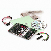
PROGRAMMER AVR STARTER KIT
Manufacturer
Atmel
Series
AVR®r
Type
MCUr
Specifications of ATSTK500
Contents
Board, Cable, CD and Documentation
Data Bus Width
8 bit
Interface Type
RS-232
For Use With/related Products
Atmel AVR Devices
For Use With
ATADAPCAN01 - EXTENSION CAN ADD-ON TO STK500/1
Lead Free Status / RoHS Status
Lead free / RoHS Compliant


3.5
AVR STK500 User Guide
Description of
User RS-232
Interface
The STK500 includes two RS-232 ports. One RS-232 port is used for communicating
with AVR Studio. The other RS-232 can be used for communicating between the target
AVR microcontroller in the socket and a PC serial port connected to the RS-232. To use
the RS-232, the UART pins of the AVR need to be physically connected to the RS-232.
The 2-pin header marked “RS232 SPARE” can be used for connecting the RS-232 con-
verter to the UART pins on the target AVR microcontroller in the socket. Use the 2-wire
cable to connect the UART pins to the RS-232. The connection is shown in Figure 3-9.
The block schematic of the RS-232 connection is shown in Figure 3-10.
Figure 3-9. Connection of I/O Pins to UART
Figure 3-10. Schematic of UART Pin Connections
TXD
RXD
VTG
Converter
Voltage
5V
MAX202CSE
5V
470R
470R
1n2
1n2
Hardware Description
1925C–AVR–3/03
RS-232
3
2
3-5
Related parts for ATSTK500
Image
Part Number
Description
Manufacturer
Datasheet
Request
R

Part Number:
Description:
DEV KIT FOR AVR/AVR32
Manufacturer:
Atmel
Datasheet:

Part Number:
Description:
INTERVAL AND WIPE/WASH WIPER CONTROL IC WITH DELAY
Manufacturer:
ATMEL Corporation
Datasheet:
Part Number:
Description:
Low-Voltage Voice-Switched IC for Hands-Free Operation
Manufacturer:
ATMEL Corporation
Datasheet:
Part Number:
Description:
MONOLITHIC INTEGRATED FEATUREPHONE CIRCUIT
Manufacturer:
ATMEL Corporation
Datasheet:
Part Number:
Description:
AM-FM Receiver IC U4255BM-M
Manufacturer:
ATMEL Corporation
Datasheet:
Part Number:
Description:
Monolithic Integrated Feature Phone Circuit
Manufacturer:
ATMEL Corporation
Datasheet:
Part Number:
Description:
Multistandard Video-IF and Quasi Parallel Sound Processing
Manufacturer:
ATMEL Corporation
Datasheet:
Part Number:
Description:
High-performance EE PLD
Manufacturer:
ATMEL Corporation
Datasheet:
Part Number:
Description:
8-bit Flash Microcontroller
Manufacturer:
ATMEL Corporation
Datasheet:
Part Number:
Description:
2-Wire Serial EEPROM
Manufacturer:
ATMEL Corporation
Datasheet: