AT91SAM9260-EK Atmel, AT91SAM9260-EK Datasheet - Page 23
AT91SAM9260-EK
Manufacturer Part Number
AT91SAM9260-EK
Description
KIT EVAL FOR AT91SAM9260
Manufacturer
Atmel
Series
AT91SAM Smart ARMr
Type
MCUr
Datasheets
1.AT91SAM9260-EK.pdf
(47 pages)
2.AT91SAM9260-EK.pdf
(39 pages)
3.AT91SAM9260-EK.pdf
(10 pages)
Specifications of AT91SAM9260-EK
Contents
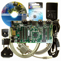
Evaluation Board, Parallel Cable and CD-ROM
Processor To Be Evaluated
AT91SAM9260
Data Bus Width
32 bit
Interface Type
RS-232, Ethernet, USB
Core
ARM 9
Silicon Manufacturer
Atmel
Core Architecture
ARM
Core Sub-architecture
ARM926EJ-S
Silicon Core Number
AT91SAM9260
Silicon Family Name
ARM
Kit Contents
Board, Cables, CD, Power Supply
Rohs Compliant
Yes
For Use With/related Products
AT91SAM9260
Lead Free Status / RoHS Status
Lead free / RoHS Compliant


4.5
4.6
AT91SAM9260-EK Evaluation Board User Guide
Ethernet
Miscellaneous
RMII is the factory default mode.
To evaluate the MII mode, the user has to unsolder R49, R50, R127 and close S7 and
S8.
When the RMII mode is used, the user can use the specific MII signals as PIO, but the
following resistors must be unsoldered (R119 to R126).
Refer to the TOP level schematic for the PIO usage.
Table 4-5.
Designation
R82
R72
R73
R94
R95
R96
R98
R101
R103
R104
R105
R106
R83
R85
R86
R88
TP1
TP2
TP3
TP4
TP5
TP6
Default
Setting
Soldered
Soldered
Soldered
Soldered
Soldered
Soldered
Soldered
N.A
N.A
N.A
N.A
N.A
N.A
Feature
USB DEVICE: Enables the use of the USBCNX signal
DBGU COM Port: Enables the use of DTXD output
signalEnables the use of DRXD input
RS232 COM Port 0: Enable the use of outputs signal
RTS0
TXD0
DTR0
RS232 COM Port 0: Enable the use of inputs signal
DCD0
DSR0
RXD0
CTS0
RI0
Enables all MAX3241E outputs buffer
RS232 COM Port 1: Enable the use of outputs signal
TXD1
RTS1
RS232 COM Port 1: Enable the use of inputs signal
RXD1
CTS1
GND Test point
GND Test point.
GND Test point.
GND Test point.
Reserved: do not use
Reserved: do not use
6234C–ATARM–22-Mar-07
Configuration
4-3
Related parts for AT91SAM9260-EK
Image
Part Number
Description
Manufacturer
Datasheet
Request
R

Part Number:
Description:
MCU, MPU & DSP Development Tools KICKSTART KIT FOR AT91SAM9 PLUS
Manufacturer:
IAR Systems

Part Number:
Description:
DEV KIT FOR AVR/AVR32
Manufacturer:
Atmel
Datasheet:

Part Number:
Description:
INTERVAL AND WIPE/WASH WIPER CONTROL IC WITH DELAY
Manufacturer:
ATMEL Corporation
Datasheet:
Part Number:
Description:
Low-Voltage Voice-Switched IC for Hands-Free Operation
Manufacturer:
ATMEL Corporation
Datasheet:
Part Number:
Description:
MONOLITHIC INTEGRATED FEATUREPHONE CIRCUIT
Manufacturer:
ATMEL Corporation
Datasheet:
Part Number:
Description:
AM-FM Receiver IC U4255BM-M
Manufacturer:
ATMEL Corporation
Datasheet:
Part Number:
Description:
Monolithic Integrated Feature Phone Circuit
Manufacturer:
ATMEL Corporation
Datasheet:
Part Number:
Description:
Multistandard Video-IF and Quasi Parallel Sound Processing
Manufacturer:
ATMEL Corporation
Datasheet:
Part Number:
Description:
High-performance EE PLD
Manufacturer:
ATMEL Corporation
Datasheet:
Part Number:
Description:
8-bit Flash Microcontroller
Manufacturer:
ATMEL Corporation
Datasheet:
Part Number:
Description:
2-Wire Serial EEPROM
Manufacturer:
ATMEL Corporation
Datasheet: