QSK-62P PLUS BNS Solutions, QSK-62P PLUS Datasheet - Page 48
QSK-62P PLUS
Manufacturer Part Number
QSK-62P PLUS
Description
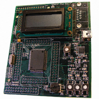
KIT QUICK START RENESAS 62P
Manufacturer
BNS Solutions
Series
M16C™r
Type
MCUr
Datasheet
1.QSK-62P_PLUS.pdf
(103 pages)
Specifications of QSK-62P PLUS
Contents
Board, Cable, CD
For Use With/related Products
M16C/62P
Lead Free Status / RoHS Status
Not applicable / Not applicable
Other names
867-1000
QSK-62P
QSK26A
QSK62P
QSK-62P
QSK26A
QSK62P


M16C/62P Group (M16C/62P, M16C/62PT)
Rev.2.41
REJ03B0001-0241
Table 5.9
NOTES:
Table 5.10
NOTES:
V
V
V
V
V
t
t
t
t
t
d(P-R)
d(R-S)
d(W-S)
d(S-R)
d(E-A)
det4
det3
det4
det3s
det3r
Symbol
Symbol
1. V
2. Where reset level detection voltage is less than 2.7 V, if the supply power voltage is greater than the reset level detection
3. V
4. The voltage detection circuit is designed to use when VCC1 is set to 5V.
1. When V
-V
det3
voltage, the microcomputer operates with f(BCLK) ≤ 10MHz.
det4
det3r
Jan 10, 2006
> V
> V
Low Voltage Detection Voltage
Reset Level Detection Voltage
Electric potential difference of Low Voltage
Detection and Reset Level Detection
Low Voltage Reset Retention Voltage
Low Voltage Reset Release Voltage
Time for Internal Power Supply Stabilization
During Powering-On
STOP Release Time
Low Power Dissipation Mode Wait Mode
Release Time
Brown-out Detection Reset (Hardware Reset 2)
Release Wait Time
Low Voltage Detection Circuit Operation Start
Time
CC1
det3
det3
Low Voltage Detection Circuit Electrical Characteristics
Power Supply Circuit Timing Characteristics
= 5V.
.
is not guaranteed.
Page 46 of 96
Parameter
Parameter
(1, 2)
(1)
(3)
V
V
V
V
CC1
CC1
CC1
CC1
Measuring Condition
Measuring Condition
=0.8V to 5.5V
=2.7V to 5.5V
=V
=2.7V to 5.5V
det3r
to 5.5V
Min.
Min.
3.3
2.2
0.3
2.2
5. Electrical Characteristics
Standard
Standard
Typ.
Typ.
6
3.8
2.8
2.9
(1)
Max.
Max.
150
150
4.4
3.6
0.8
4.0
20
20
2
Unit
Unit
ms
ms
µ s
µ s
µ s
V
V
V
V
V