DV164136 Microchip Technology, DV164136 Datasheet - Page 2

DV164136
Manufacturer Part Number
DV164136
Description
DEVELOPMENT KIT FOR PIC18
Manufacturer
Microchip Technology
Series
PIC®r
Type
MCUr
Datasheets
1.DM183032.pdf
(38 pages)
2.DV164136.pdf
(448 pages)
3.DV164136.pdf
(6 pages)
4.DV164136.pdf
(446 pages)
5.DV164136.pdf
(4 pages)
6.DV164136.pdf
(18 pages)
Specifications of DV164136
Contents
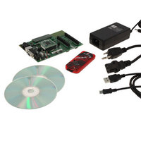
Board, Cables, CDs, PICkit™ 3 Programmer, Power Supply
Processor To Be Evaluated
PIC18F8722, PIC18F87J11
Interface Type
RS-232, USB
Operating Supply Voltage
3.3 V, 5 V
Silicon Manufacturer
Microchip
Core Architecture
PIC
Core Sub-architecture
PIC18
Silicon Core Number
PIC18F
Silicon Family Name
PIC18F8xxx
Kit Contents
PIC18 Exp Brd PICkit 3 Cable CD PSU
Lead Free Status / RoHS Status
Lead free / RoHS Compliant
For Use With/related Products
PIC18F8722, PIC18F87J11
Lead Free Status / Rohs Status
Lead free / RoHS Compliant
Available stocks
Company
Part Number
Manufacturer
Quantity
Price
Company:
Part Number:
DV164136
Manufacturer:
MICROCHIP
Quantity:
12 000
PIC18F6627/6722/8627/8722
4. Module: MSSP (I
5. Module: Enhanced Universal
DS80343B-page 2
If the module is in I
performs clock stretching, the first clock pulse after
the slave releases the SCL line may be narrower
than the configured clock width. This may result in
the slave missing the first clock in the next
transmission/reception.
Work around
If the module is in I
the slave perform clock stretching. Alternately, the
master can slow down the SCL clock frequency to
a level where the slave can detect the narrowed
clock pulse.
Date Codes that pertain to this issue:
All engineering and production devices.
In rare situations when interrupts are enabled,
unexpected results may occur if:
• The EUSART is disabled (the SPEN
• The EUSART is re-enabled (RCSTAx <7> = 1)
• A two-cycle instruction is executed
Work around
Add a 2-T
1.
2.
3.
4.
5.
Date Codes that pertain to this issue:
All engineering and production devices.
(RCSTAx <7>) bit = 0)
Disable the receive interrupts:
• For RCSTA1 – RC1IE bit (PIE1<5>) = 0
• For RCSTA2 – RC2IE bit (PIE3<5>) = 0
Disable the EUSART:
• For RCSTA1 – SPEN bit (RCSTA1<7>) = 0
• For RCSTA2 – SPEN bit (RCSTA2<7>) = 0
Re-enable the EUSART (RCSTAx <7> = 1).
(See step 1.)
Re-enable the receive interrupts:
• For RCSTA1 – RC1IE bit (PIE1<5>) = 1
• For RCSTA2 – RC2IE bit (PIE3<5>) = 1
Execute a NOP instruction.
(This is the second T
(This is the first T
CY
Synchronous Asynchronous
(EUSART)
delay after re-enabling the EUSART.
2
2
C Master mode and the slave
2
C Master mode, do not have
C™ Master)
CY
CY
delay.)
delay.)
6. Module: Timer1
When Timer1 is running on the Timer1 oscillator, if
Sleep mode is executed immediately after loading
Timer 1 with 0xFFFF, the Timer1 interrupt will not
get set on the first overflow from 0xFFFF to
0x0000.
All subsequent overflows, from 0xFFFF to 0x0000,
will work correctly.
Work around
None.
Date Codes that pertain to this issue:
All engineering and production devices.
© 2009 Microchip Technology Inc.


