AT89STK-11 Atmel, AT89STK-11 Datasheet - Page 11
AT89STK-11
Manufacturer Part Number
AT89STK-11
Description
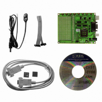
KIT STARTER FOR AT89C51RX2
Manufacturer
Atmel
Type
MCUr
Datasheet
1.AT89STK-11.pdf
(23 pages)
Specifications of AT89STK-11
Contents
Evaluation Board, Software and Documentation
Processor To Be Evaluated
AT89C51Rx
Interface Type
RS-232, SPI, TWI
For Use With/related Products
AT89C51Rx2
Lead Free Status / RoHS Status
Lead free / RoHS Compliant


3.1
3.1.1
3.1.2
3.2
3.2.1
AT89STK-11 Hardware User Guide
Manual ISP Mode
Board Configuration
Operating Mode
Auto ISP Mode
Board Configuration
The On-Chip memories and configuration bytes can be programmed using the ISP
mode of the device and Atmel's FLexible In-system Programmer Software (FLIP)
described below.
See Section “FLIP Software”, page 11.
To use ISP mode, no specific configuration is necessary on the board. Only make sure
that the EA pin of the product is tied to Vcc (internal code execution only).
To enter in ISP mode, press both the RESET and ISP buttons simultaneously.
First release the RESET button and then the ISP button. The device enters in
ISP mode.
It allows the host PC application (Atmel Flip software for example) to control the hard-
ware conditions from the serial lines RTS and DTR.
Thus with the Auto ISP mode, the user does not need to push the ISP and RESET
buttons.
To use Auto ISP mode, put the board in the same configuration as ISP mode and also:
Close RTS (J11) jumper
Close DTR (J12) jumper
ISP Programming
Section 3
7676B–8051–08/07
3-10
Related parts for AT89STK-11
Image
Part Number
Description
Manufacturer
Datasheet
Request
R

Part Number:
Description:
KIT EVAL APPL MASS STORAGE
Manufacturer:
Atmel
Datasheet:

Part Number:
Description:
KIT STARTER FOR AT89C5131
Manufacturer:
Atmel
Datasheet:

Part Number:
Description:
KIT DEMOBOARD 8051 MCU W/CAN
Manufacturer:
Atmel
Datasheet:

Part Number:
Description:
KIT STARTER FOR AT83C24
Manufacturer:
Atmel
Datasheet:

Part Number:
Description:
EVAL BOARD FOR AT83C26
Manufacturer:
Atmel
Datasheet:

Part Number:
Description:
KIT STARTER FOR MCU AT8XC5122/23
Manufacturer:
Atmel
Datasheet:


Part Number:
Description:
8-Bit Microcontroller with 4K Bytes Flash
Manufacturer:
ATMEL Corporation
Datasheet:

Part Number:
Description:
DEV KIT FOR AVR/AVR32
Manufacturer:
Atmel
Datasheet:
Part Number:
Description:
INTERVAL AND WIPE/WASH WIPER CONTROL IC WITH DELAY
Manufacturer:
ATMEL Corporation
Datasheet:
Part Number:
Description:
Low-Voltage Voice-Switched IC for Hands-Free Operation
Manufacturer:
ATMEL Corporation
Datasheet:
Part Number:
Description:
MONOLITHIC INTEGRATED FEATUREPHONE CIRCUIT
Manufacturer:
ATMEL Corporation
Datasheet:
Part Number:
Description:
AM-FM Receiver IC U4255BM-M
Manufacturer:
ATMEL Corporation
Datasheet:
Part Number:
Description:
Monolithic Integrated Feature Phone Circuit
Manufacturer:
ATMEL Corporation
Datasheet: