DM300024 Microchip Technology, DM300024 Datasheet - Page 39
DM300024
Manufacturer Part Number
DM300024
Description
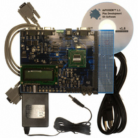
KIT DEMO DSPICDEM 1.1
Manufacturer
Microchip Technology
Type
MCUr
Specifications of DM300024
Contents
Board, Cable, CD, Power Supply
Silicon Manufacturer
Microchip
Core Architecture
DsPIC
Core Sub-architecture
DsPIC30F
Features
Serial Communication Channels Interface, General Purpose Prototyping Area
Silicon Core Number
DsPIC30F, DsPIC33F
Silicon Family Name
DsPIC30F6xxx, DsPIC33FJxxGPxxx
Rohs Compliant
Yes
Lead Free Status / RoHS Status
Lead free / RoHS Compliant
For Use With/related Products
dsPIC30F/33F and PIC24H
Lead Free Status / RoHS Status
Lead free / RoHS Compliant, Lead free / RoHS Compliant
Available stocks
Company
Part Number
Manufacturer
Quantity
Price
Company:

Part Number:
DM300024
Manufacturer:
MICROCHIP
Quantity:
12 000


© 2006 Microchip Technology Inc.
dsPIC30F Demonstration Program Operation
Each DTMF tone consists of two sinusoids: a high-frequency component and a low-
frequency component. In the DTMF tones implemented for this demonstration, the
high-frequency component is at a level 8 dB lower than the low-frequency component.
You can listen to the generated tones by using either a headset or a passive speaker
connected to the “SPKR OUT” jack (J17).
If you connected your PC for the Data Acquisition Display demo (see Section 3.3.1.1),
you can use the <0>-<9> keys on the PC keyboard to select a DTMF tone.
To quit this demonstration and return to Menu Options, press switch SW1.
3.3.2
The following two sections summarize the key dsPIC30F MCU, DSP and peripheral
features implemented in this general purpose demonstration program.
3.3.2.1
The demonstration program uses several unique dsPIC30F MCU/DSP features for
various processing functions, including:
• DSP Engine for FFT, FIR and IIR computations
• Bit-Reversed Addressing for 256-point FFT input data in preparation for the FFT
• Modulo Addressing for accessing arrays in a circular fashion for FIR filtering
• Hardware Loop instructions
• Program Space Visibility (PSV)
3.3.2.2
The demonstration program also implements several dsPIC30F peripherals for various
tasks. These peripherals include:
• Timer1 – Configured as a 16-bit timer
• Timer2 – Configured as 16-bit timer with a 256:1 prescaler
• Timer3 – Configured as 16-bit timer with a 256:1 prescaler
• Timer4 and Timer5 – Configured as a 32-bit timer
• UART2 TX/RX – Used to transmit demo data to the PC and receive commands
• SPI 2 – Used to communicate to the 122 x 32 Addressable-Pixel LCD via the
• 12-bit ADC – Used to convert multiple analog signals, including temperature and
- 40-bit accumulators with Saturation, Overflow and Rounding modes
- Multiply-and-Accumulate (MAC) class of DSP instructions
“butterfly” computations
- Two modulo buffers have been implemented, one each in X and Y data
- DO and REPEAT instructions provide minimal overhead when executing a
- Large tables for FIR filter coefficients, sine tables etc., are stored in and
from the PC keyboard
PIC18F242 LCD controller and MCP41010 digital potentiometer
sine-wave signals generated by the MCP41010 digital potentiometer through a
low-pass filter
Note:
spaces.
block of instructions repetitively.
accessed from program memory.
Demonstrated Features and Peripherals
dsPIC30F MCU/DSP FEATURES
dsPIC30F DEMO PERIPHERALS
For a passive speaker, use a Radio Shack Model # 40-1434 Fold-up Stereo
Speaker System or an equivalent device.
DS70099D-page 35
Related parts for DM300024
Image
Part Number
Description
Manufacturer
Datasheet
Request
R

Part Number:
Description:
Manufacturer:
Microchip Technology Inc.
Datasheet:
Part Number:
Description:
Manufacturer:
Microchip Technology Inc.
Datasheet:
Part Number:
Description:
Manufacturer:
Microchip Technology Inc.
Datasheet:
Part Number:
Description:
Manufacturer:
Microchip Technology Inc.
Datasheet:
Part Number:
Description:
Manufacturer:
Microchip Technology Inc.
Datasheet:
Part Number:
Description:
Manufacturer:
Microchip Technology Inc.
Datasheet:
Part Number:
Description:
Manufacturer:
Microchip Technology Inc.
Datasheet:
Part Number:
Description:
Manufacturer:
Microchip Technology Inc.
Datasheet: