DM300024 Microchip Technology, DM300024 Datasheet - Page 70
DM300024
Manufacturer Part Number
DM300024
Description
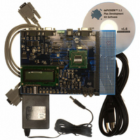
KIT DEMO DSPICDEM 1.1
Manufacturer
Microchip Technology
Type
MCUr
Specifications of DM300024
Contents
Board, Cable, CD, Power Supply
Silicon Manufacturer
Microchip
Core Architecture
DsPIC
Core Sub-architecture
DsPIC30F
Features
Serial Communication Channels Interface, General Purpose Prototyping Area
Silicon Core Number
DsPIC30F, DsPIC33F
Silicon Family Name
DsPIC30F6xxx, DsPIC33FJxxGPxxx
Rohs Compliant
Yes
Lead Free Status / RoHS Status
Lead free / RoHS Compliant
For Use With/related Products
dsPIC30F/33F and PIC24H
Lead Free Status / RoHS Status
Lead free / RoHS Compliant, Lead free / RoHS Compliant
Available stocks
Company
Part Number
Manufacturer
Quantity
Price
Company:

Part Number:
DM300024
Manufacturer:
MICROCHIP
Quantity:
12 000


dsPICDEM™ 1.1 Plus Development Board User’s Guide
DS70099D-page 66
Oscillator selection parameters are shown in Table 5-2.
TABLE 5-2:
5.1.16
By placing J10 jumper in the MCLR1 position, the Reset switch connected to the
processor MCLR pin provides a hard Reset to the dsPIC DSC device. By placing J10
jumper in the MCLR2 position, the Reset switch is connected to the PIC18F242 LCD
controller.
The Reset switch circuit is shown in Figure A-2: “dsPICDEM™ 1.1 Plus Develop-
ment Board Schematic (Sheet 1 of 5)”.
5.1.17
A prototyping area and associated header are provided on the development board to
enable additional ICs and attachment boards to be added (see Figure
A-2: “dsPICDEM™ 1.1 Plus Development Board Schematic (Sheet 1 of 5)”).
5.1.18
A sample dsPIC DSC device programmed with the demonstration code is included in
the dsPICDEM™ 1.1 Plus Development Board Kit. The 80-pin TQFP is soldered to a
1.5” x 1.5” adaptor PCB, which is inserted onto the emulation header, J11 and J13-J15.
Handle the device carefully when inserting and extracting the adaptor board. The
orientation of the adaptor board is important. The Microchip logo and device part
numbering should be aligned to read from left to right before insertion of the adaptor
board. The pin 1 index marker of dsPIC30F device should align with the lower left
45° corner of the 80-pin QFP footprint (pin 1 of Emulation Header J14).
Pin-out information for the emulation header is shown in Figure A-2: “dsPICDEM™
1.1 Plus Development Board Schematic (Sheet 1 of 5)”.
Crystal (X3)
Mini Crystal (X2)
Canned Oscillator (U5)
RC
External Clock
Note
Oscillator Selection on
dsPICDEM™ 1.1 Plus
1:
Demo Board
Reset Switch
Prototyping Area
Sample Devices
The oscillator circuit schematics are shown in Figure
A-2: “dsPICDEM™ 1.1 Plus Development Board Schematic (Sheet 1
of 5)”
OSCILLATOR SELECTION PARAMETERS
R33, R34, R20, C20, C21 and X2 open, U5 empty.
Crystal in X3, caps in C33 and C37.
R20, R33, R34, C33, C37 and X1 open, U5 empty.
Crystal in X2, caps in C20 and C21.
R20, R33, R34, C20, C21, C33, C37, X2 and X3 open,
U5 installed.
R33, R34, C20, C21, C33, X2 and X3 open, U5 empty.
Cap in C37 and resistor in R20.
R20, C20, C21, C33, C37, U5, X2 and X3 open. 0 ohm
installed for R33 and R34.
Modifications on dsPICDEM™ 1.1 Plus Demo Board
© 2006 Microchip Technology Inc.
(1)
Related parts for DM300024
Image
Part Number
Description
Manufacturer
Datasheet
Request
R

Part Number:
Description:
Manufacturer:
Microchip Technology Inc.
Datasheet:
Part Number:
Description:
Manufacturer:
Microchip Technology Inc.
Datasheet:
Part Number:
Description:
Manufacturer:
Microchip Technology Inc.
Datasheet:
Part Number:
Description:
Manufacturer:
Microchip Technology Inc.
Datasheet:
Part Number:
Description:
Manufacturer:
Microchip Technology Inc.
Datasheet:
Part Number:
Description:
Manufacturer:
Microchip Technology Inc.
Datasheet:
Part Number:
Description:
Manufacturer:
Microchip Technology Inc.
Datasheet:
Part Number:
Description:
Manufacturer:
Microchip Technology Inc.
Datasheet: