AT91RM3400-DK Atmel, AT91RM3400-DK Datasheet - Page 7
AT91RM3400-DK
Manufacturer Part Number
AT91RM3400-DK
Description
KIT DEV FOR AT91RM3400
Manufacturer
Atmel
Series
AT91SAM Smart ARMr
Type
MCUr
Datasheets
1.AT91RM3400-DK.pdf
(461 pages)
2.AT91RM3400-DK.pdf
(2 pages)
3.AT91RM3400-DK.pdf
(25 pages)
Specifications of AT91RM3400-DK
Contents
Evaluation Board, Software and Documentation
Processor To Be Evaluated
AT91RM3400
Data Bus Width
32 bit
Interface Type
RS-232, USB
For Use With/related Products
AT91RM3400
Lead Free Status / RoHS Status
Contains lead / RoHS non-compliant


2.1
2.2
2.3
2.4
AT91RM3400 Development Kit User Guide
Electrostatic
Warning
Requirements
Powering Up the
Board
Getting Started
with the
AT91RM3400
The AT91RM3400 development board is shipped in protective anti-static packaging.
The board must not be subjected to high electrostatic potentials. A grounding strap or
similar protective device should be worn when handling the board. Avoid touching the
component pins or any other metallic element.
In order to connect the AT91RM3400 development board, the following elements are
required:
DC power is supplied to the board via the 2.1 mm socket (J1). The polarity of the power
supply is not critical. The minimum voltage required is 7V.
The board has a voltage regulator providing +3.3V. The regulator allows the input volt-
age range to be from 7V to 12V.
The AT91RM3400 Development Kit is delivered with a CD-ROM containing all neces-
sary information and step-by-step procedures for working with the most common
development tool chains.
Please refer to this CD-ROM, or to the AT91 web site, http://www.atmel.com/prod-
ucts/AT91/, for the most up-to-date information on getting started with the
AT91RM3400.
The AT91RM3400 development board itself
Power supply cable capable of supplying 7V to 12V at 1A (not supplied)
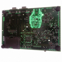
Setting Up the AT91RM3400
Development Board
Section 2
Rev. 6106A–ATARM–09/04
2-1
Related parts for AT91RM3400-DK
Image
Part Number
Description
Manufacturer
Datasheet
Request
R

Part Number:
Description:
DEV KIT FOR AVR/AVR32
Manufacturer:
Atmel
Datasheet:

Part Number:
Description:
INTERVAL AND WIPE/WASH WIPER CONTROL IC WITH DELAY
Manufacturer:
ATMEL Corporation
Datasheet:
Part Number:
Description:
Low-Voltage Voice-Switched IC for Hands-Free Operation
Manufacturer:
ATMEL Corporation
Datasheet:
Part Number:
Description:
MONOLITHIC INTEGRATED FEATUREPHONE CIRCUIT
Manufacturer:
ATMEL Corporation
Datasheet:
Part Number:
Description:
AM-FM Receiver IC U4255BM-M
Manufacturer:
ATMEL Corporation
Datasheet:
Part Number:
Description:
Monolithic Integrated Feature Phone Circuit
Manufacturer:
ATMEL Corporation
Datasheet:
Part Number:
Description:
Multistandard Video-IF and Quasi Parallel Sound Processing
Manufacturer:
ATMEL Corporation
Datasheet:
Part Number:
Description:
High-performance EE PLD
Manufacturer:
ATMEL Corporation
Datasheet:
Part Number:
Description:
8-bit Flash Microcontroller
Manufacturer:
ATMEL Corporation
Datasheet:
Part Number:
Description:
2-Wire Serial EEPROM
Manufacturer:
ATMEL Corporation
Datasheet: