DC-ME-9210-NET Digi International, DC-ME-9210-NET Datasheet - Page 24
DC-ME-9210-NET
Manufacturer Part Number
DC-ME-9210-NET
Description
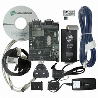
KIT JUMP START ME 9210 NET+OS 7
Manufacturer
Digi International
Series
Digi Connect ME®r
Type
MCU Moduler
Datasheets
1.DC-ME-01T-S.pdf
(4 pages)
2.DC-ME-Y401-JT.pdf
(4 pages)
3.DC-ME-Y401-JT.pdf
(66 pages)
4.DC-ME-9210-NET.pdf
(2 pages)
Specifications of DC-ME-9210-NET
Contents
Board, Cables, CD, Digi JTAG Link Hardware Debugger, Documentation, Module, Power Supply
Data Rate
10 Mbps to 100 Mbps
Memory Type
SDRAM
Interface Type
RS-232, Ethernet
Operating Voltage
12 V
Operating Current
346 mA
Maximum Power Dissipation
825 mW
Operating Temperature Range
- 40 C to + 80 C
Board Size
36.7 mm x 19.05 mm
Data Bus Width
32 bit
Modulation
CCK, DBPSK, DQPSK
Product
Modules
Security
64/128 bit WEP, TKIP, WPA, WPA2
Silicon Manufacturer
Digi Intl
Kit Application Type
Communication & Networking
Application Sub Type
Embedded
Silicon Family Name
Digi Connect ME
Rohs Compliant
Yes
For Use With/related Products
Digi Connect ME 9210 Module
Lead Free Status / RoHS Status
Lead free / RoHS Compliant
Other names
602-1136


Module JTAG Interface Connector, P11
JTAG Debugger Connector, P12
Note:
Note:
The Module JTAG Interface Connector is a 14-pin female vertical header that is labeled
P11 on the development board. The connector mates with the JTAG connector on the Digi
Connect ME embedded module. The Module JTAG Connector pins are tied to the JTAG
debugger Connector (see “JTAG Debugger Connector, P12”).
Note:
The JTAG debugger connector is a 20-pin male vertical header that is labeled P12 on the
development board. The connector mates with a JTAG debugger plug (for example, a Digi
JTAG Link). The connector is used with the development kit only. See the following figure
for pin orientation. See the following table for pin assignments.
Note:
Pin
19
20
The Digi Connect Wi-ME module does not provide pins 1-6
See "Module Pinout" on page 33 for detailed IO configuration information.
Because there is no direct connection to the Module JTAG Interface
Connector, pin orientation and pin assignments are not described for the
connector.
The figure shows the connector using the same orientation as shown in the
figure titled "Board Layout and Connector Locations:" on page 17.
/INIT
ME
Module Connector Pin Assignments
Signal
/INIT
Wi-ME
Reserved
Digi Plug-and-Play Firmware Software
Reset
Description
2 4
Related parts for DC-ME-9210-NET
Image
Part Number
Description
Manufacturer
Datasheet
Request
R

Part Number:
Description:
ME 9210 8MB SDRAM 4MB FLASH SGL
Manufacturer:
Digi International
Datasheet:

Part Number:
Description:
ENCRYPTION ENGINE 10/100 INT
Manufacturer:
Digi International
Datasheet:

Part Number:
Description:
ME 8MB SDRAM 2MB FLASH SINGLE
Manufacturer:
Digi International
Datasheet:

Part Number:
Description:
ME 8MB SDRAM 2MB FLASH SINGLE
Manufacturer:
Digi International
Datasheet:

Part Number:
Description:
ME 8MB SDRAM 2MB FLASH 10 PAK
Manufacturer:
Digi International
Datasheet:

Part Number:
Description:
ME 8MB SDRAM 2MB FLASH 10 PAK
Manufacturer:
Digi International
Datasheet:

Part Number:
Description:
MOD ME 9210 8MB SDRAM 2MB FLASH
Manufacturer:
Digi International
Datasheet:

Part Number:
Description:
MOD ME 9210 8MB SDRAM 4MB FLASH
Manufacturer:
Digi International
Datasheet:
Part Number:
Description:
MODULE ME CUSTOMIZABLE JTAG
Manufacturer:
Digi International
Datasheet:
Part Number:
Description:
MODULE ME 8MB SDRAM 2MB FLASH
Manufacturer:
Digi International
Datasheet:
Part Number:
Description:
MODULE ME 8MB SDRAM 2MB FLASH
Manufacturer:
Digi International
Datasheet:

Part Number:
Description:
ME 9210 8MB RAM 4MB FLASH LINUX
Manufacturer:
Digi International
Datasheet:
Part Number:
Description:
ME 8MB SDRAM 2MB FLASH 50 PAK
Manufacturer:
Digi International
Datasheet:
Part Number:
Description:
ME 8MB SDRAM 2MB FLASH 50 PAK
Manufacturer:
Digi International
Datasheet:
Part Number:
Description:
MODULE ME 8MB SDRAM 2MB FLASH
Manufacturer:
Digi International
Datasheet: