ADZS-21469-EZBRD Analog Devices Inc, ADZS-21469-EZBRD Datasheet - Page 9
ADZS-21469-EZBRD
Manufacturer Part Number
ADZS-21469-EZBRD
Description
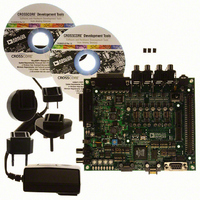
KIT EVAL EZ BOARD ADSP-21469
Manufacturer
Analog Devices Inc
Series
SHARC®r
Type
DSPr
Datasheet
1.ADZS-21469-EZBRD.pdf
(62 pages)
Specifications of ADZS-21469-EZBRD
Contents
Board
Silicon Manufacturer
Analog Devices
Core Architecture
SHARC
Features
External JTAG Emulator, Standalone Debug Agent Board
Kit Contents
Board Cables CD Docs
Silicon Core Number
ADSP-21469
Silicon Family Name
SHARC
Rohs Compliant
Yes
Lead Free Status / RoHS Status
Lead free / RoHS Compliant
For Use With/related Products
ADSP-2146x
Lead Free Status / RoHS Status
Lead free / RoHS Compliant, Lead free / RoHS Compliant


Preliminary Technical Data
lines. Bank 0 occupies a 14M word window and banks 1, 2, and
3 occupy a 16M word window in the processor’s address space
but, if not fully populated, these windows are not made contigu-
ous by the memory controller logic.
The asynchronous memory controller is capable of a maximum
throughput of TBD Mbps using a TBD MHz external bus speed.
Other features include 8 to 32-bit packing and unpacking, boot-
ing from bank select 1, and support for delay line DMA.
INPUT/OUTPUT FEATURES
The ADSP-21462W, ADSP-21465W and ADSP-21469W I/O
processors provide 67 channels of DMA, while ADSP-21467
and ADSP-21469 I/O processors provide 36 channels of DMA
as well as an extensive set of peripherals. These include a 20 lead
digital applications interface, which controls:
The ADSP-2146x processor also contains a 14 lead digital
peripheral interface, which controls:
DMA Controller
The processor’s on-chip DMA controller allows data transfers
without processor intervention. The DMA controller operates
independently and invisibly to the processor core, allowing
DMA operations to occur while the core is simultaneously exe-
cuting its program instructions. DMA transfers can occur
between the ADSP-2146x’s internal memory and its serial ports,
the SPI-compatible (serial peripheral interface) ports, the IDP
(input data port), the parallel data acquisition port (PDAP) or
the UART.
Sixty-seven channels of DMA are available on the
ADSP-21462W, ADSP-21465W and ADSP-21469W devices,
and thirty-six channels on the ADSP-21467 and ADSP-21469.
The breakdown is as follows: 16 via the serial ports, eight via the
input data port, two for the UART, two for the SPI interface,
two for the external port, two for DTCP (or memory-to-mem-
ory data transfer when DTCP is not used), two for the link port,
two for the FFT/FIR/IIR accelerators, and up to 31 DMA chan-
nels for the media local bus interface on the ADSP-21462W,
ADSP-21465W and ADSP-21469W.
Programs can be downloaded to the ADSP-2146x using DMA
transfers. Other DMA features include interrupt generation
upon completion of DMA transfers, and DMA chaining for
automatic linked DMA transfers.
• Eight serial ports
• S/PDIF receiver/transmitter
• Four precision clock generators
• Input data port/parallel data acquisition port
• Four asynchronous sample rate converters
• Two general-purpose timers
• Two serial peripheral interfaces
• One universal asynchronous receiver/transmitter (UART)
• An I
• Two PCGs (C and D) can also be routed through DPI
2
C
®
-compatible 2-wire interface
Rev. PrC | Page 9 of 62 | January 2009
ADSP-21462/ADSP-21465/ADSP-21467/ADSP-21469
Delay Line DMA
The ADSP-2146x processor provides delay line DMA function-
ality. This allows processor reads and writes to external delay
line buffers (and hence to external memory) with limited core
interaction.
Scatter/Gather DMA
The ADSP-2146x processor provides scatter/gather DMA
functionality.
This allows processor DMA reads/writes to/from non-contin-
geous memory blocks.
Digital Applications Interface (DAI)
The digital applications interface (DAI) provides the ability to
connect various peripherals to any of the DAI pins
(DAI_P20–1).
Programs make these connections using the signal routing unit
(SRU), shown in
The SRU is a matrix routing unit (or group of multiplexers) that
enables the peripherals provided by the DAI to be intercon-
nected under software control. This allows easy use of the DAI
associated peripherals for a much wider variety of applications
by using a larger set of algorithms than is possible with noncon-
figurable signal paths.
The DAI also includes eight serial ports, four precision clock
generators (PCG), S/PDIF transceiver, four ASRCs, and an
input data port (IDP). The IDP provides an additional input
path to the SHARC core, configurable as either eight channels
of serial data, or a single 20-bit wide synchronous parallel data
acquisition port. Each data channel has its own DMA channel
that is independent from the processor’s serial ports.
Serial Ports
The ADSP-2146x features eight synchronous serial ports that
provide an inexpensive interface to a wide variety of digital and
mixed-signal peripheral devices such as Analog Devices’
AD183x family of audio codecs, ADCs, and DACs. The serial
ports are made up of two data lines, a clock, and frame sync. The
data lines can be programmed to either transmit or receive and
each data line has a dedicated DMA channel.
Serial ports can support up to 16 transmit or 16 receive channels
of audio data when all eight SPORTs are enabled, or four full
duplex TDM streams of 128 channels per frame.
The serial ports operate at a maximum data rate of 56.25 Mbps.
Serial port data can be automatically transferred to and from
on-chip memory/external memory via dedicated DMA chan-
nels. Each of the serial ports can work in conjunction with
another serial port to provide TDM support. One SPORT pro-
vides two transmit signals while the other SPORT provides the
two receive signals. The frame sync and clock are shared.
Serial ports operate in five modes:
• Standard DSP serial mode
• Multichannel (TDM) mode
• I
2
S mode
Figure
1.
Related parts for ADZS-21469-EZBRD
Image
Part Number
Description
Manufacturer
Datasheet
Request
R

Part Number:
Description:
KIT EVAL EZ LITE ADSP-21469
Manufacturer:
Analog Devices Inc
Datasheet:

Part Number:
Description:
USB EZ-Extender For Blackfin And SHARC EZ-Boards/EZ-KIT Lites
Manufacturer:
Analog Devices Inc

Part Number:
Description:
±1.7g Dual-Axis IMEMS Accelerometer Evaluation Board
Manufacturer:
Analog Devices Inc
Datasheet:
Part Number:
Description:
Inertial Sensor Evaluation System
Manufacturer:
Analog Devices Inc
Datasheet:
Part Number:
Description:
Manufacturer:
Analog Devices Inc
Datasheet:
Part Number:
Description:
Manufacturer:
Analog Devices Inc
Datasheet:
Part Number:
Description:
Manufacturer:
Analog Devices Inc
Datasheet:
Part Number:
Description:
Manufacturer:
Analog Devices Inc
Datasheet:
Part Number:
Description:
Manufacturer:
Analog Devices Inc
Datasheet:
Part Number:
Description:
Manufacturer:
Analog Devices Inc
Datasheet:
Part Number:
Description:
Manufacturer:
Analog Devices Inc
Datasheet:
Part Number:
Description:
Manufacturer:
Analog Devices Inc
Datasheet:
Part Number:
Description:
Manufacturer:
Analog Devices Inc
Datasheet: