C8051F226DK Silicon Laboratories Inc, C8051F226DK Datasheet - Page 140
C8051F226DK
Manufacturer Part Number
C8051F226DK
Description
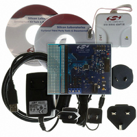
DEV KIT F220/221/226/230/231/236
Manufacturer
Silicon Laboratories Inc
Type
MCUr
Datasheet
1.C8051F226DK.pdf
(146 pages)
Specifications of C8051F226DK
Contents
Evaluation Board, Power Supply, USB Cables, Adapter and Documentation
Processor To Be Evaluated
C8051F22x and C8051F23x
Interface Type
USB
Silicon Manufacturer
Silicon Labs
Core Architecture
8051
Silicon Core Number
C8051F226
Silicon Family Name
C8051F2xx
Lead Free Status / RoHS Status
Contains lead / RoHS non-compliant
For Use With/related Products
C8051F220, 221, 226, 230, 231, 236
Lead Free Status / Rohs Status
Lead free / RoHS Compliant
Other names
336-1241


C8051F2xx
18.1. Flash Programming Commands
The Flash memory can be programmed directly over the JTAG interface using the Flash Control, Flash
Data, Flash Address, and Flash Scale registers. These Indirect Data Registers are accessed via the JTAG
Instruction Register. Read and write operations on indirect data registers are performed by first setting the
appropriate DR address in the IR register. Each read or write is then initiated by writing the appropriate
Indirect Operation Code (IndOpCode) to the selected data register. Incoming commands to this register
have the following format:
IndOpCode: These bit set the operation to perform according to the following table:
The Poll operation is used to check the Busy bit as described below. Although a Capture-DR is performed,
no Update-DR is allowed for the Poll operation. Since updates are disabled, polling can be accomplished
by shifting in/out a single bit.
The Read operation initiates a read from the register addressed by the DRAddress. Reads can be initiated
by shifting only 2 bits into the indirect register. After the read operation is initiated, polling of the Busy bit
must be performed to determine when the operation is complete.
The write operation initiates a write of WriteData to the register addressed by DRAddress. Registers of
any width up to 18 bits can be written. If the register to be written contains fewer than 18 bits, the data in
WriteData should be left-justified, i.e. its MSB should occupy bit 17 above. This allows shorter registers to
be written in fewer JTAG clock cycles. For example, an 8-bit register could be written by shifting only 10
bits. After a Write is initiated, the Busy bit should be polled to determine when the next operation can be
initiated. The contents of the Instruction Register should not be altered while either a read or write opera-
tion is in progress.
Outgoing data from the indirect Data Register has the following format:
The Busy bit indicates that the current operation is not complete. It goes high when an operation is initi-
ated and returns low when complete. Read and Write commands are ignored while Busy is high. In fact, if
polling for Busy to be low will be followed by another read or write operation, JTAG writes of the next oper-
ation can be made while checking for Busy to be low. They will be ignored until Busy is read low, at which
time the new operation will initiate. This bit is placed at bit 0 to allow polling by single-bit shifts. When wait-
ing for a Read to complete and Busy is 0, the following 18 bits can be shifted out to obtain the resulting
data. ReadData is always right-justified. This allows registers shorter than 18 bits to be read using a
reduced number of shifts. For example, the result from a byte-read requires 9 bit shifts (Busy + 8 bits).
140
IndOpCode
19:18
19
0
IndOpCode
10
0x
11
Rev. 1.6
ReadData
18:5
Operation
WriteData
Read
Write
Poll
17:0
Busy
0
Related parts for C8051F226DK
Image
Part Number
Description
Manufacturer
Datasheet
Request
R

Part Number:
Description:
SMD/C°/SINGLE-ENDED OUTPUT SILICON OSCILLATOR
Manufacturer:
Silicon Laboratories Inc
Part Number:
Description:
Manufacturer:
Silicon Laboratories Inc
Datasheet:
Part Number:
Description:
N/A N/A/SI4010 AES KEYFOB DEMO WITH LCD RX
Manufacturer:
Silicon Laboratories Inc
Datasheet:
Part Number:
Description:
N/A N/A/SI4010 SIMPLIFIED KEY FOB DEMO WITH LED RX
Manufacturer:
Silicon Laboratories Inc
Datasheet:
Part Number:
Description:
N/A/-40 TO 85 OC/EZLINK MODULE; F930/4432 HIGH BAND (REV E/B1)
Manufacturer:
Silicon Laboratories Inc
Part Number:
Description:
EZLink Module; F930/4432 Low Band (rev e/B1)
Manufacturer:
Silicon Laboratories Inc
Part Number:
Description:
I°/4460 10 DBM RADIO TEST CARD 434 MHZ
Manufacturer:
Silicon Laboratories Inc
Part Number:
Description:
I°/4461 14 DBM RADIO TEST CARD 868 MHZ
Manufacturer:
Silicon Laboratories Inc
Part Number:
Description:
I°/4463 20 DBM RFSWITCH RADIO TEST CARD 460 MHZ
Manufacturer:
Silicon Laboratories Inc
Part Number:
Description:
I°/4463 20 DBM RADIO TEST CARD 868 MHZ
Manufacturer:
Silicon Laboratories Inc
Part Number:
Description:
I°/4463 27 DBM RADIO TEST CARD 868 MHZ
Manufacturer:
Silicon Laboratories Inc
Part Number:
Description:
I°/4463 SKYWORKS 30 DBM RADIO TEST CARD 915 MHZ
Manufacturer:
Silicon Laboratories Inc
Part Number:
Description:
N/A N/A/-40 TO 85 OC/4463 RFMD 30 DBM RADIO TEST CARD 915 MHZ
Manufacturer:
Silicon Laboratories Inc
Part Number:
Description:
I°/4463 20 DBM RADIO TEST CARD 169 MHZ
Manufacturer:
Silicon Laboratories Inc