DEMO908QC16 Freescale Semiconductor, DEMO908QC16 Datasheet - Page 6
DEMO908QC16
Manufacturer Part Number
DEMO908QC16
Description
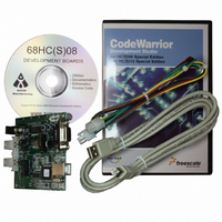
BOARD DEMO FOR MC908QC16
Manufacturer
Freescale Semiconductor
Type
MCUr
Specifications of DEMO908QC16
Contents
Board, Cable, CD
Processor To Be Evaluated
MC908QC16
Data Bus Width
8 bit
Interface Type
RS-232, USB
Silicon Manufacturer
Freescale
Core Architecture
HC08
Core Sub-architecture
HC08
Silicon Core Number
MC68HC908
Silicon Family Name
HC08Q
Kit Contents
Board
Rohs Compliant
No
For Use With/related Products
MC908QC16
Lead Free Status / RoHS Status
Contains lead / RoHS non-compliant


D E M O 9 0 8 Q C 1 6
•
Specifications:
Board Size 3.1” x 3.2”
REFERENCES
Reference documents are provided on the support CD in Acrobat Reader format.
DEMO908QC16_UG.pdf
DEMO908QC16_SCH_A.pdf
DEMO908QC16QS.pdf
DEMO908QC16_LED.zip
DEMO908QC16_ATD.zip
AN2627.pdf
GETTING STARTED
To get started quickly, please refer to the DEMO908QC16 Quick Start Guide. This quick start
will illustrate how to connect the board to the PC, run a LED test program, install the correct
version of CodeWarrior Development Studio, and load an Analog to Digital (ATD) test program
using CodeWarrior.
OPERATING MODES
The DEMO908QC16 board operates in two basic modes Run Mode, or MON08 Debug Mode.
Run Mode allows the user application to execute from Power-On or Reset. MON08 Debug
Mode allows the development and debug of applications via the MON08 embedded debug
monitor. See the related sections below for quickly starting the board in the desired operating
mode. The board has been preloaded with a demonstration program that operates in Run
Mode. The +5V LED will light when power is applied to the board.
RUN Mode
Run mode allows the user application to execute when power is applied to the board or the
RESET button is pressed. Use the following settings to configure the DEMO908QC16 board
for RUN Mode using the USB bus to power the board.
1. Connect a serial communication cable (not included) between the board and a host PC if
•
•
Supplied with USB Cable, LIN Cable, Documentation (CD), and Manual.
needed.
Power Input: 9VDC typical, +7VDC to +18VDC
DB9 Serial Connector
2, 4-pos LIN Connectors
NOTE: LIN functionality enabled only when powered from PWR connector.
DEMO908QC16 User Guide (this document)
DEMO908QC16 Board Schematic Rev. A
DEMO908QC16 Quick Start Guide
CodeWarrior LED Demonstration application
CodeWarrior ATD Demonstration application
Cycle-by-Cycle Instruction Details for HC08 MCU’s
6
J U N E
2 0 ,
2 0 0 5
Related parts for DEMO908QC16
Image
Part Number
Description
Manufacturer
Datasheet
Request
R

Part Number:
Description:
Manufacturer:
STMicroelectronics
Datasheet:

Part Number:
Description:
DEMO BOARD FOR HMC6042/HMC1041Z
Manufacturer:
Honeywell Microelectronics & Precision Sensors

Part Number:
Description:
DEMO BOARD FOR HMC1042L/HMC1041Z
Manufacturer:
Honeywell Microelectronics & Precision Sensors
Datasheet:

Part Number:
Description:
KIT DEMO 4 SENSOR CHAN RS232
Manufacturer:
VTI Technologies
Datasheet:


Part Number:
Description:
DEMO: DC Power Supply, 32 Volts, 3 Amps
Manufacturer:
Tektronix
Part Number:
Description:
DEMO: Programmable DC Power Supply, 32 Volts, 3 Amps
Manufacturer:
Tektronix

Part Number:
Description:
Manufacturer:
Freescale Semiconductor, Inc
Datasheet:
Part Number:
Description:
Manufacturer:
Freescale Semiconductor, Inc
Datasheet:
Part Number:
Description:
Manufacturer:
Freescale Semiconductor, Inc
Datasheet:
Part Number:
Description:
Manufacturer:
Freescale Semiconductor, Inc
Datasheet:
Part Number:
Description:
Manufacturer:
Freescale Semiconductor, Inc
Datasheet:
Part Number:
Description:
Manufacturer:
Freescale Semiconductor, Inc
Datasheet:
Part Number:
Description:
Manufacturer:
Freescale Semiconductor, Inc
Datasheet:
Part Number:
Description:
Manufacturer:
Freescale Semiconductor, Inc
Datasheet: