DEMOQE128 Freescale Semiconductor, DEMOQE128 Datasheet - Page 13
DEMOQE128
Manufacturer Part Number
DEMOQE128
Description
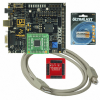
DEMO BOARD FOR QE128 FLEXIS
Manufacturer
Freescale Semiconductor
Series
Flexis™r
Type
MCUr
Specifications of DEMOQE128
Contents
Demo Board, USB Cable, Documentation and Design Files
Processor To Be Evaluated
MC9S08QE128 and MCF51QE128
Data Bus Width
8 bit, 32 bit
Interface Type
RS-232, USB
Silicon Manufacturer
Freescale
Core Architecture
Coldfire, HCS08
Core Sub-architecture
Coldfire V1, HCS08
Silicon Core Number
MCF51Q, MC9S08
Rohs Compliant
Yes
Tool Type
Demonstration Board
Cpu Core
HCS08
For Use With/related Products
MC9S08QE128, MCF51QE128
For Use With
DEMOACEX - BOARD EXPANSION FOR DEMO KIT
Lead Free Status / RoHS Status
Lead free / RoHS Compliant
Available stocks
Company
Part Number
Manufacturer
Quantity
Price
Company:

Part Number:
DEMOQE128
Manufacturer:
Freescale Semiconductor
Quantity:
135
Company:
Part Number:
DEMOQE128
Manufacturer:
NINEX
Quantity:
3 500


3.2
DEMOQE128 User Manual
LAB 1: Learn How to use DEMOQE Toolkit Utilities
STEP 4: TEST BOARD BY RUNNING QUICK START APPLICATION
Now that you have successfully completed the software and hardware setup,
test your board by interacting with the Quick Start Application that is pre-
loaded in the microcontroller’s on-chip flash memory.
The programmed application samples the microcontroller’s general purpose
input pins. These pins are connected to push buttons and perform two
actions. The first action is to illuminate the respective LED with either a
general purpose output pin or a pulse-width modulated signal pin. The second
action is to play a different tone per push button on the speaker, using a
pulse-width modulated signal programmed at different frequencies. The
application samples the potentiometer using the microcontroller’s analog-to-
digital converter and uses the result to vary the light intensity of two LEDs by
changing their pulse-width modulated signal’s duty cycle.
This lab will show you how to use one of several graphical utilities in
DEMOQE Toolkit included with your board. Instructions to download these
utilities to your computer are provided in Step 2 of the Section 3.1 - Quick
Start Guide. Make sure to use only one utility at a time, as the utilities all
share the same USB resource. The toolkit utilities may be used at the same
1. Turn the SYSTEM POWER switch to the ON position. The red
2. Press push buttons labeled PTA2, PTA3, PTD2, and PTD3. A differ-
3. Rotate the potentiometer (W1) to vary the light intensity of the LEDs
4. Now that your board is functional, try out the provided labs in
POWER LED will illuminate and the application will start automati-
cally.
ent tone will be emitted from speaker when each push button is
pressed, and the corresponding LEDs labeled PTC1, PTC2, PTC3,
and PTC4 will illuminate.
labeled PTC0 and PTC5.
DEMOQE128 Labs section to learn more about the Flexis QE128
microcontrollers and other features included with your board.
9
Related parts for DEMOQE128
Image
Part Number
Description
Manufacturer
Datasheet
Request
R

Part Number:
Description:
DEM FOR STM8L15X LOW PWR MODES
Manufacturer:
STMicroelectronics
Datasheet:

Part Number:
Description:
Manufacturer:
Freescale Semiconductor, Inc
Datasheet:
Part Number:
Description:
Manufacturer:
Freescale Semiconductor, Inc
Datasheet:
Part Number:
Description:
Manufacturer:
Freescale Semiconductor, Inc
Datasheet:
Part Number:
Description:
Manufacturer:
Freescale Semiconductor, Inc
Datasheet:
Part Number:
Description:
Manufacturer:
Freescale Semiconductor, Inc
Datasheet:
Part Number:
Description:
Manufacturer:
Freescale Semiconductor, Inc
Datasheet:
Part Number:
Description:
Manufacturer:
Freescale Semiconductor, Inc
Datasheet:
Part Number:
Description:
Manufacturer:
Freescale Semiconductor, Inc
Datasheet:
Part Number:
Description:
Manufacturer:
Freescale Semiconductor, Inc
Datasheet:
Part Number:
Description:
Manufacturer:
Freescale Semiconductor, Inc
Datasheet:
Part Number:
Description:
Manufacturer:
Freescale Semiconductor, Inc
Datasheet:
Part Number:
Description:
Manufacturer:
Freescale Semiconductor, Inc
Datasheet:
Part Number:
Description:
Manufacturer:
Freescale Semiconductor, Inc
Datasheet:
Part Number:
Description:
Manufacturer:
Freescale Semiconductor, Inc
Datasheet: