DEMOQE128 Freescale Semiconductor, DEMOQE128 Datasheet - Page 30
DEMOQE128
Manufacturer Part Number
DEMOQE128
Description
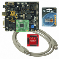
DEMO BOARD FOR QE128 FLEXIS
Manufacturer
Freescale Semiconductor
Series
Flexis™r
Type
MCUr
Specifications of DEMOQE128
Contents
Demo Board, USB Cable, Documentation and Design Files
Processor To Be Evaluated
MC9S08QE128 and MCF51QE128
Data Bus Width
8 bit, 32 bit
Interface Type
RS-232, USB
Silicon Manufacturer
Freescale
Core Architecture
Coldfire, HCS08
Core Sub-architecture
Coldfire V1, HCS08
Silicon Core Number
MCF51Q, MC9S08
Rohs Compliant
Yes
Tool Type
Demonstration Board
Cpu Core
HCS08
For Use With/related Products
MC9S08QE128, MCF51QE128
For Use With
DEMOACEX - BOARD EXPANSION FOR DEMO KIT
Lead Free Status / RoHS Status
Lead free / RoHS Compliant
Available stocks
Company
Part Number
Manufacturer
Quantity
Price
Company:

Part Number:
DEMOQE128
Manufacturer:
Freescale Semiconductor
Quantity:
135
Company:
Part Number:
DEMOQE128
Manufacturer:
NINEX
Quantity:
3 500


5.3
5.4
6
6.1
26
DEMOQE TOOLKIT PC APPLICATIONS
Run Mode
External BDM Mode
DEMOQE Logic Analyzer Application
DEMOQE128 CODE DEVELOPMENT SOFTWARE for more information.
The DEMOQE128’s rich component list empowers it to perform a variety of
tasks. Once an application is developed, debugged, and programmed
properly into the QE128 internal flash memory, it can run with or without
connecting to a host.
The DEMOQE128 has an optional BDM header for debugging and
programming the on-board QE128 device using an external BDM hardware
tool, such as P&E’s USB Multilink or Cyclone PRO. Please refer to Section
10 - TRANSITIONING TO YOUR OWN TARGET for more information. A user
can take advantage of this mode to develop a target-specific QE128 system
and compare it with the DEMOQE128 when necessary.
P&E provides several Windows PC-based applications which work with the
DEMOQE128 board. These applications are collectively referred to as the
DEMOQE Toolkit. The following applications are included in the toolkit:
The DEMOQE board has a built-in two-channel logic analyzer. This analyzer
allows the IN0 and IN1 signals to be captured by the PC and displayed for the
user. The IN0 and IN1 signals may be connected to any of the MCU signals
which the user would like to view. By default, they are connected to the PTC0
and PTC1 pins of the MCU by jumper J11. At the time of this release, the logic
analyzer runs at a capture rate of 10khz.
DEMOQE128 User Manual
Related parts for DEMOQE128
Image
Part Number
Description
Manufacturer
Datasheet
Request
R

Part Number:
Description:
DEM FOR STM8L15X LOW PWR MODES
Manufacturer:
STMicroelectronics
Datasheet:

Part Number:
Description:
Manufacturer:
Freescale Semiconductor, Inc
Datasheet:
Part Number:
Description:
Manufacturer:
Freescale Semiconductor, Inc
Datasheet:
Part Number:
Description:
Manufacturer:
Freescale Semiconductor, Inc
Datasheet:
Part Number:
Description:
Manufacturer:
Freescale Semiconductor, Inc
Datasheet:
Part Number:
Description:
Manufacturer:
Freescale Semiconductor, Inc
Datasheet:
Part Number:
Description:
Manufacturer:
Freescale Semiconductor, Inc
Datasheet:
Part Number:
Description:
Manufacturer:
Freescale Semiconductor, Inc
Datasheet:
Part Number:
Description:
Manufacturer:
Freescale Semiconductor, Inc
Datasheet:
Part Number:
Description:
Manufacturer:
Freescale Semiconductor, Inc
Datasheet:
Part Number:
Description:
Manufacturer:
Freescale Semiconductor, Inc
Datasheet:
Part Number:
Description:
Manufacturer:
Freescale Semiconductor, Inc
Datasheet:
Part Number:
Description:
Manufacturer:
Freescale Semiconductor, Inc
Datasheet:
Part Number:
Description:
Manufacturer:
Freescale Semiconductor, Inc
Datasheet:
Part Number:
Description:
Manufacturer:
Freescale Semiconductor, Inc
Datasheet: