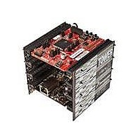
TWR-MCF5225X-KIT Freescale Semiconductor, TWR-MCF5225X-KIT Datasheet - Page 7

TWR-MCF5225X-KIT
Manufacturer Part Number
TWR-MCF5225X-KIT
Description
KIT TOWER BRD/SER/ELEV MCF5225X
Manufacturer
Freescale Semiconductor
Series
ColdFire®r
Type
MCUr
Specifications of TWR-MCF5225X-KIT
Contents
4 Boards, Cable, DVD
Processor To Be Evaluated
MCF5225X
Data Bus Width
8 bit, 16 bit, 32 bit
Interface Type
Ethernet, USB
Operating Supply Voltage
3.3 V, 5 V
Silicon Manufacturer
Freescale
Core Architecture
Coldfire
Core Sub-architecture
Coldfire V2
Silicon Core Number
MCF52
Silicon Family Name
MCF5225x
Kit Contents
Board
Rohs Compliant
Yes
For Use With/related Products
Freescale Tower System
Lead Free Status / RoHS Status
Lead free / RoHS Compliant
Jumper
Quick Start Guide for TWR-MCF5225X
Quick Start Guide for TWR-MCF5225X
J11
J12
J13
J14
J15
J16
J20
J21
TCLK/PSTCLK/CLKOUT
TCLK/PSTCLK Routing
UART Hardware Flow
UART RXD0 Routing
Control Connections
UART TXD0 Routing
OSBDM Bootloader
BDM/JTAG Enable
Routing Selection
RESET Select
Selection
Selection
Selection
Selection
Selection
Option
Setting
OFF
OFF
1-2
3-4
1-2
2-3
1-2
2-3
1-2
2-3
1-2
2-3
1-2
2-3
ON
ON
Connect CTS0 to the RS232 transciever for flow control
Connect RTS0 to the RS232 transciever for flow control
Connect TXD0 to the RS232 transceiver
Connect TXD0 to the OSBDM debugger interface circuit
Connect RXD0 to the RS232 transceiver
Connect RXD0 to the OSBDM debugger interface circuit
BDM mode
JTAG mode
Connect TCLK/PSTCLK to PSTCLK for BDM mode
Connect TCLK/PSTCLK to TCLK for JTAG mode
Connect TCLK/PSTCLK/CLKOUT to TCLK/PSTCLK for
BDM/JTAG mode
Connect TCLK/PSTCLK/CLKOUT to CLKOUT0 on the
elevator connector
OSBDM bootloader mode (OSBDM
firmware reprogramming)
Debugger mode
Suspend MCU in reset state (hold RSTIN low)
Release RSTIN so it can be controlled by SW4 to
initiate reset sequences
Description
TOWER SYSTEM
TOWER SYSTEM


