M53015EVB Freescale Semiconductor, M53015EVB Datasheet - Page 9
M53015EVB
Manufacturer Part Number
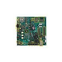
M53015EVB
Description
KIT DEVELOPMENT FOR MCF53015
Manufacturer
Freescale Semiconductor
Type
MPUr
Specifications of M53015EVB
Contents
Board, Cables, Cards, Power Supply Kit
Processor To Be Evaluated
MCF5301
Data Bus Width
32 bit
Interface Type
Ethernet, USB, UART, SPI, I2C
Maximum Operating Temperature
+ 85 C
Minimum Operating Temperature
- 40 C
Operating Supply Voltage
3.6 V
Silicon Manufacturer
Freescale
Core Architecture
Coldfire
Core Sub-architecture
Coldfire V3
Silicon Core Number
MCF53
Silicon Family Name
MCF5301x
Rohs Compliant
Yes
For Use With/related Products
MCF53015
Lead Free Status / RoHS Status
Lead free / RoHS Compliant


5.17
The MCF53015 has 2 10/100 Ethernet MACs. On the M53015EVB these are each connected to National
Semiconductor DP83640 ethernet PHYs. A dual port Ethernet jack, P2, is provided. Ethernet Channel 1 is
connected to the upper port, while Channel 0 is connected to the lower port. Link, speed, and activity lights
are provided for each port. MAC addresses for each Ethernet port are labeled on the board. The DP83640
also supports IEEE 1588. These pins are provided on a 26 pin header, J2.
5.18
The MCF53015 includes 3 UART modules. The M53015EVB provides one standard RS232 line driver
necessary to interface with RS232 connectors. This driver is connected to the DB9 connector J52 and
jumper options can connect the driver to either UART1 (muxed with the SSI port pins) or UART2
(dedicated). The board also supplies a USB-to-UART bridge to interface with the MCF53015’s UART0.
If using this option, a USB type B connector can be used to interface with an external device, instead of
the standard RS232 connector. Before using this connector, the Serial to USB bridge driver
“CP210x_VCP_Win2K_XP_S2K3.exe” should be installed. This driver can be found on the included
DVD. Once the driver is installed, the USB port will show up on your computer as a COM port and you
can communicate with it using any terminal program. You can view the Device Manager on your computer
to determine the assigned COM port. UART jumper configurations are described in the following tables:
Freescale Semiconductor
Communicate with UART1 through
the DB9 connector J52 (4 pin UART)
Communicate with UART2 through
the DB9 connector J52 (2 pin UART)
Ethernet
UARTs
Function
HDSTN/HDSTP lines from internal codec connected
directly to the headset jack
DACN/DACP lines from internal codec connected to
the line out jack through filter circuitry
LOUT/ROUT lines from external codec connected to
the line out jack through filter circuitry
Table 7. UART1 and UART2 Configuration
Table 6. Headset/Line Out Configuration
M53015 Evaluation Board, Rev. 0.5
Function
1-2
J5
X
1-2
J6
X
1-2
J7
X
J34
1-2
2-3
3-4
1-2
J8
X
J35
1-2
2-3
3-4
J12
2-3
1-2
J13
2-3
1-2
9
Related parts for M53015EVB
Image
Part Number
Description
Manufacturer
Datasheet
Request
R

Part Number:
Description:
Manufacturer:
Freescale Semiconductor, Inc
Datasheet:
Part Number:
Description:
Manufacturer:
Freescale Semiconductor, Inc
Datasheet:
Part Number:
Description:
Manufacturer:
Freescale Semiconductor, Inc
Datasheet:
Part Number:
Description:
Manufacturer:
Freescale Semiconductor, Inc
Datasheet:
Part Number:
Description:
Manufacturer:
Freescale Semiconductor, Inc
Datasheet:
Part Number:
Description:
Manufacturer:
Freescale Semiconductor, Inc
Datasheet:
Part Number:
Description:
Manufacturer:
Freescale Semiconductor, Inc
Datasheet:
Part Number:
Description:
Manufacturer:
Freescale Semiconductor, Inc
Datasheet:
Part Number:
Description:
Manufacturer:
Freescale Semiconductor, Inc
Datasheet:
Part Number:
Description:
Manufacturer:
Freescale Semiconductor, Inc
Datasheet:
Part Number:
Description:
Manufacturer:
Freescale Semiconductor, Inc
Datasheet:
Part Number:
Description:
Manufacturer:
Freescale Semiconductor, Inc
Datasheet:
Part Number:
Description:
Manufacturer:
Freescale Semiconductor, Inc
Datasheet:
Part Number:
Description:
Manufacturer:
Freescale Semiconductor, Inc
Datasheet:
Part Number:
Description:
Manufacturer:
Freescale Semiconductor, Inc
Datasheet: