XCARD XC-1A XMOS, XCARD XC-1A Datasheet
XCARD XC-1A
Specifications of XCARD XC-1A


Related parts for XCARD XC-1A


XCARD XC-1A Summary of contents
Page 1
... XC-1A Hardware Manual Publication Date: 2010/04/27 Copyright © 2010 XMOS Ltd. All Rights Reserved. Version 1.2 ...
Page 2
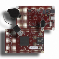
... XC-1A Hardware Manual (1.2) 1 Introduction The XC- card-sized development board based on the XMOS XS1-G4 event-driven processor device. It comprises a single XS1-G4, 16 user-configurable LEDs, four push- buttons, a speaker, JTAG and serial interfaces, four expansion areas suitable for IDC headers and a through-hole prototyping area for connecting external components. ...
Page 3
... The other 12 LEDs are positioned around the XS1- circle (collectively referred to as clock-LEDs) and contain red/green diodes. A Roman numeral is printed next to each LED. The layout of the LEDs is shown on the following page. www.xmos.com 3/18 ...
Page 4
... IIII X0D40 X0D41 X0D42 X1D40 PORT_CLOCKLED_0 PORT_CLOCKLED_1 PORT_CLOCKLED_SELR PORT_CLOCKLED_SELG get yellow, alternate green/red in 4:1 ratio III V VI VII VIII X1D41 X1D42 X2D40 X2D41 X2D42 X3D40 PORT_CLOCKLED_2 Colour 0 Off 1 Green 0 Red 1 Red www.xmos.com XII X3D41 X3D42 PORT_CLOCKLED_3 PORT_CLOCKLED_SELG X0D12 PORT_CLOCKLED_SELR X0D13 4/18 ...
Page 5
... P1F0 PORT_CLOCKLED_SELR P8D4 PORT_CLOCKLED_1 [IV] P8D5 PORT_CLOCKLED_1 [V] P8D6 PORT_CLOCKLED_1 [VI] P8D4 PORT_CLOCKLED_2 [VII] P8D5 PORT_CLOCKLED_2 [VIII] P8D6 PORT_CLOCKLED_2 [IX] P8D4 PORT_CLOCKLED_3 [X] P8D5 PORT_CLOCKLED_3 [XI] P8D6 PORT_CLOCKLED_3 [XII] Pin Port Processor 4b 0 X0D14 P4C0 PORT_BUTTONLED [A] X0D15 P4C1 PORT_BUTTONLED [B] X0D20 P4C2 PORT_BUTTONLED [C] X0D21 P4C3 PORT_BUTTONLED [D] www.xmos.com 5/18 ...
Page 6
... The default state of a pin is high, pushing the button drives its pin low. Each pin can be interfaced to a 4-bit port or an 8-bit port on the XS1-G4. The choice is defined by the port interface used in the software [2 Port Processor P4D0 P8B2 PORT_BUTTON [A] P4D1 P8B3 PORT_BUTTON [B] P4D2 P8B4 PORT_BUTTON [C] P4D3 P8B5 PORT_BUTTON [D] www.xmos.com 6/18 ...
Page 7
... Eight pins from each bank can be configured as either two 4-bit ports or a single 8-bit port. Alternatively, two of the expansion headers can be used together as a single 16-bit port. X3D12 X3D14 X3D16 X3D18 X3D20 X2D22 X2D10 www.xmos.com 7/ X3D13 X3D15 X3D17 3V3 GND X3D19 ...
Page 8
... P8A5 P16A5 P4A2 P8A6 P16A6 P4A3 P8A7 P16A7 P1C0 P1D0 P1E0 P1F0 P4C0 P8B0 P16A8 P4C1 P8B1 P16A9 P4D0 P8B2 P16A10 P4D1 P8B3 P16A11 X3PortB P4D2 P8B4 P16A12 P4D3 P8B5 P16A13 P4C2 P8B6 P16A14 P4C3 P8B7 P16A15 P1G0 P1H0 www.xmos.com 8/18 ...
Page 9
... XC-1A Hardware Manual (1.2) 5.1 XMOS Link Configuration Some of the I/O pins on the expansion header can be configured as XMOS Links. The mapping of XMOS Links to the headers is shown in the table below. Pin Processor 1 2 bit XnD1 XnD2 XnD3 XnD4 XLA1 I XnD5 ...
Page 10
... X0D37 X0D36 X0D33 X0D32 X0D31 X0D30 X0D29 X0D28 X0D27 X0D26 X0D11 X0D10 X0D1 X0D0 GND 5V Port Processor P4E0 P8C0 P4E1 P8C1 P4F0 P8C2 P4F1 P8C3 P4F2 P8C4 P4F3 P8C5 Prototyping Area P4E2 P8C6 P4E3 P8C7 P1M0 P1N0 P1O0 P1P0 www.xmos.com 10/18 ...
Page 11
... Audio signals are generated by filtering pulse width modulated (PWM) digital signals to form an analogue waveform, which is amplified and sent to the speaker, as shown below: X0D34 The speaker pin is mapped to a port on processor 0, as shown in the table below. FILTER AMPLIFIER Pin Port Processor 1b 0 X0D34 P1K0 PORT_SPEAKER www.xmos.com 11/18 SPEAKER ...
Page 12
... COM port to the PC that can be interfaced via a terminal emulator. 9 20MHz Crystal Oscillator [I] The XS1-G4 is clocked at 20MHz by a crystal oscillator on the card. Each processor is clocked at 400MHz, the I/O ports at 100MHz on-chip phase-locked loop (PLL). Pin Port Processor 1b 0 X0D23 P1H0 PORT_UART_TX X0D24 P1I0 PORT_UART_RX www.xmos.com 12/18 ...
Page 13
... The layout of the connector is shown below. 12 Dimensions The XC-1A dimensions are 86 x 54mm. The mounting holes are 3mm in diameter. Pin Port Processor 1b 0 X0D0 P1A0 PORT_SPI_MISO X0D1 P1B0 PORT_SPI_SS X0D10 P1C0 PORT_SPI_CLK X0D11 P1D0 PORT_SPI_MOSI www.xmos.com 13/18 ...
Page 14
... The table on the next page provides a full description of the port-to-pin mappings described throughout this document. Processor 1 Processor 2 A I/O HEADER A I/O HEADER A XS1-G4 System Services SS_RESET RST 3V3 CLOCK 20MHz XTO www.xmos.com 14/18 Processor I/O HEADER A/B PORT_UART_RX PORT_UART_TX SS_TDO SS_TDI SS_TMS SS_TCK SS_TRST SS_DEBUG ...
Page 15
... TESTPOINT UART_TX UART_RX TESTPOINT PROTO_AREA_4 PROTO_AREA_5 PROTO_AREA_6 PROTO_AREA_7 PROTO_AREA_8 PROTO_AREA_9 PROTO_AREA_10 PROTO_AREA_11 SPEAKER TESTPOINT PROTO_AREA_12 PROTO_AREA_13 PROTO_AREA_14 PROTO_AREA_15 CLOCKLED_0 [I] CLOCKLED_1 [IV] CLOCKLED_2 [VII] CLOCKLED_0 [II] CLOCKLED_1 [V] CLOCKLED_0 [III] CLOCKLED_1 [VI] CLOCKLED_2 [IX] www.xmos.com 15/ X2PortA X3PortA Header Header X3PortB Header CLOCKLED_3 [X] CLOCKLED_2 [VIII] CLOCKLED_3 [XI] CLOCKLED_3 [XII] ...
Page 16
... The following table lists the defined identifiers for all processors: Processor Port Location Generic Identifier XS1_PORT_1A PORT_SPI_MISO XS1_PORT_1B PORT_SPI_SS XS1_PORT_1C PORT_SPI_CLK XS1_PORT_1D PORT_SPI_MOSI XS1_PORT_1E PORT_CLOCKLED_SELG XS1_PORT_1F PORT_CLOCKLED_SELR XS1_PORT_1H PORT_UART_TX XS1_PORT_1I PORT_UART_RX XS1_PORT_1K PORT_SPEAKER XS1_PORT_4C PORT_BUTTONLED XS1_PORT_4D PORT_BUTTON XS1_PORT_8D PORT_CLOCKLED_0 XS1_PORT_8D PORT_CLOCKLED_1 XS1_PORT_8D PORT_CLOCKLED_2 XS1_PORT_8D PORT_CLOCKLED_3 www.xmos.com 16/18 ...
Page 17
... The following documents provide more information on designing with the XC-1A: XCard-1A Tutorial [1]: provides an introduction to programming software on the XC-1A using the XC language. The XMOS XS1 Architecture [3]: provides an overview of the XS1 instruction set architecture. The most up-to-date information on the XC-1A, including board schematics and product datasheets, is available from: http://www ...
Page 18
... XMOS Ltd. is the owner or licensee of this design, code, or Information (collectively, the “Information”) and is providing it to you “AS IS” with no warranty of any kind, express or implied and shall have no liability in relation to its use. XMOS Ltd. makes no representation that the Information, or any particular implementation thereof will be free from any claims of infringement and again, shall have no liability in relation to any such claims ...