XCARD XC-1A XMOS, XCARD XC-1A Datasheet - Page 4
XCARD XC-1A
Manufacturer Part Number
XCARD XC-1A
Description
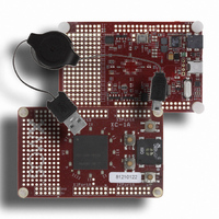
BOARD DEV KIT XS1-G4
Manufacturer
XMOS
Series
XCite™r
Type
MCUr
Specifications of XCARD XC-1A
Design Resources
XC-1A Schematic
Contents
Board, Cable
For Use With/related Products
XS1-G4
Lead Free Status / RoHS Status
Lead free / RoHS Compliant


XC-1A Hardware Manual (1.2)
To reduce the number of pins required for the 12 clock-LEDs, the LED anodes are
The schematic for the clock-LEDs is shown below
connected to four 8-bit ports (8D) on processor 0, 1, 2 and 3 and the cathodes are
connected to two 1-bit ports (1E for green, 1F for red) on processor 0.
X0D40 X0D41 X0D42
PORT_CLOCKLED_SELR
PORT_CLOCKLED_0
To get yellow, alternate green/red in 4:1 ratio
I
0
0
1
1
II
III
X1D40
PORT_CLOCKLED_SELG
PORT_CLOCKLED_1
VI
IIII
X1D41 X1D42 X2D40
0
1
0
1
V
www.xmos.com
IX
III
VI
Colour
Off
Green
Red
Red
PORT_CLOCKLED_2
VII
X2D41 X2D42 X3D40
G
G
VIII
PORT_CLOCKLED_SELG
PORT_CLOCKLED_SELR
C
B
IX
PORT_CLOCKLED_3
G
G
X
D
X0D12
X0D13
A
X3D41
XI
X3D42
XII
4/18
Related parts for XCARD XC-1A
Image
Part Number
Description
Manufacturer
Datasheet
Request
R

Part Number:
Description:
BOARD DEV KIT XS1-G4 ETHERNET
Manufacturer:
XMOS
Datasheet:

Part Number:
Description:
DEV KIT EVENT-DRIVEN PROC XS1-L1
Manufacturer:
XMOS
Datasheet:

Part Number:
Description:
BOARD KIT XS1-G4 LED CTRL TILE
Manufacturer:
XMOS
Datasheet:

Part Number:
Description:
ADAPTER USB DEBUGGER JTAG XSYS2
Manufacturer:
XMOS
Datasheet:

Part Number:
Description:
BOARD DEV KIT XS1-G4
Manufacturer:
XMOS
Datasheet:

Part Number:
Description:
IC MPU 32BIT SINGLE CORE 64LQFP
Manufacturer:
XMOS
Datasheet:

Part Number:
Description:
IC MPU 32BIT SINGLE CORE 64LQFP
Manufacturer:
XMOS
Datasheet:
Part Number:
Description:
IC MPU 32BIT SINGLE CORE 64LQFP
Manufacturer:
XMOS
Datasheet:

Part Number:
Description:
IC MPU 32BIT SINGLE CORE 64LQFP
Manufacturer:
XMOS
Datasheet:
Part Number:
Description:
IC MPU 32BIT SINGLE CORE 64LQFP
Manufacturer:
XMOS
Datasheet:

Part Number:
Description:
IC MPU 32BIT SINGLE CORE 128TQFP
Manufacturer:
XMOS
Datasheet:
Part Number:
Description:
IC MPU 32BIT SINGLE CORE 64LQFP
Manufacturer:
XMOS
Datasheet:
Part Number:
Description:
IC MPU 32BIT SINGLE CORE 128TQFP
Manufacturer:
XMOS
Datasheet:
Part Number:
Description:
IC MPU 32BIT SINGLE CORE 128TQFP
Manufacturer:
XMOS
Datasheet:

Part Number:
Description:
IC MPU 32BIT DUAL CORE 124QFN
Manufacturer:
XMOS
Datasheet: